ECD SYSTEM ECM Power Source Circuit
DESCRIPTION
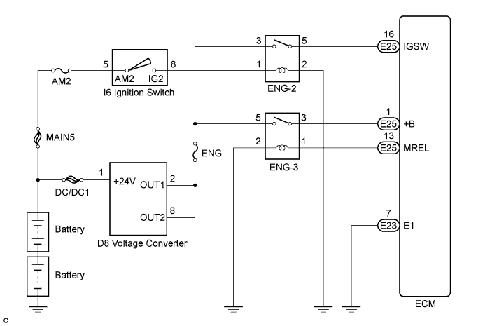
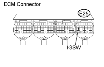
When the ignition switch is turned to the ON position, battery voltage is applied to terminal IGSW of the ECM. The ECM MREL output signal causes a current to flow to the coil, closing the contacts of the ENG-3 relay and supplying power to terminal +B of the ECM.
WIRING DIAGRAM
INSPECTION PROCEDURE
PROCEDURE
-
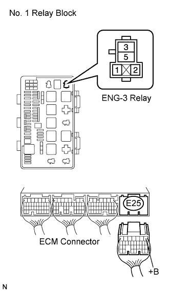
CHECK ECM (+B VOLTAGE)
-
Turn the ignition switch to the ON position.
-
Measure the voltage according to the value(s) in the table below.
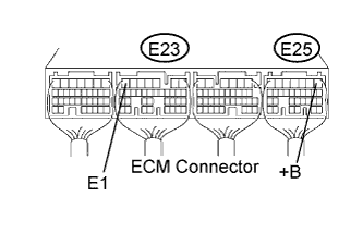
Standard voltage Tester Connection Condition Specified Condition E25-1 (+B) - E23-7 (E1) Always 11 to 14 V
NG 
CHECK HARNESS AND CONNECTOR (ECM - BODY GROUND) Click here
OK 
PROCEED TO NEXT CIRCUIT INSPECTION SHOWN IN PROBLEM SYMPTOMS TABLE
-
-
CHECK HARNESS AND CONNECTOR (ECM - BODY GROUND)
-
Disconnect ECM connector.
-
Measure the resistance according to the value(s) in the table below.
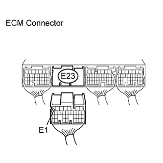
Standard resistance Tester Connection Condition Specified Condition E23-7 (E1) - Body ground Always Below 1 Ω -
Reconnect the ECM connector.
NG 
REPAIR OR REPLACE HARNESS OR CONNECTOR (ECM - BODY GROUND)
OK 
-
-
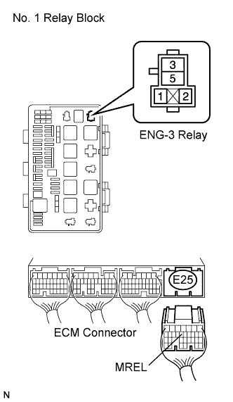
CHECK ECM (MREL VOLTAGE)
-
Turn the ignition switch to the ON position.
-
Measure the voltage according to the value(s) in the table below.
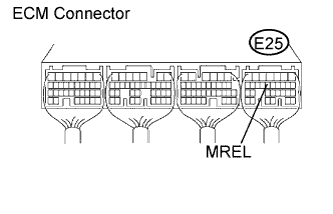
Standard voltage Tester Connection Condition Specified Condition E25-13 (MREL) - Body ground Ignition switch in the ON position 11 to 14 V
NG
CHECK ECM (IGSW VOLTAGE) Click here
OK
-
-
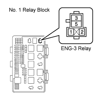
INSPECT ENG-3 RELAY
-

Remove the ENG-3 relay from the No. 1 relay block.
-
Measure the resistance according to the value(s) in the table below.
Standard resistance Tester Connection Condition Specified Condition 3 - 5 Battery voltage is not applied to terminals 1 and 2 10 kΩ or higher 3 - 5 Battery voltage is applied to terminals 1 and 2 Below 1 Ω -
Reinstall the ENG-3 relay.
NG
REPLACE ENG-3 RELAY
OK
-
-
CHECK HARNESS AND CONNECTOR (ENG-3 RELAY - ECM)
-
Remove the ENG-3 relay from the No. 1 relay block.
-
Disconnect the ECM connector.
-
Measure the resistance according to the value(s) in the table below.
Standard resistance Check for open Tester Connection Condition Specified Condition ENG-3 relay terminal 3 - E25-1 (+B) Always Below 1 Ω Check for short Tester Connection Condition Specified Condition ENG-3 relay terminal 3 or E25-1 (+B) - Body ground Always 10 kΩ or higher -
Reinstall the ENG-3 relay.
-
Reconnect the ECM connector.
NG
REPAIR OR REPLACE HARNESS OR CONNECTOR (ENG-3 RELAY - ECM)
OK
-
-
CHECK HARNESS AND CONNECTOR (ENG-3 RELAY - BODY GROUND)
-
Remove the ENG-3 relay from the No. 1 relay block.
-
Measure the resistance according to the value(s) in the table below.
Standard resistance Tester Connection Condition Specified Condition ENG-3 relay terminal 2 - Body ground Always Below 1 Ω -
Reinstall the ENG-3 relay.
NG
REPAIR OR REPLACE HARNESS OR CONNECTOR (ENG-3 RELAY - BODY GROUND)
OK
-
-
CHECK HARNESS AND CONNECTOR (ECM - ENG-3 RELAY)
-
Remove the ENG-3 relay from the No. 1 relay block.
-
Disconnect the ECM connector.
-
Measure the resistance according to the value(s) in the table below.
Standard resistance Check for open Tester Connection Condition Specified Condition E25-13 (MREL) - ENG-3 relay terminal 1 Always Below 1 Ω Check for short Tester Connection Condition Specified Condition E25-13 (MREL) or ENG-3 relay terminal 1 - Body ground Always 10 kΩ or higher -
Reinstall the ENG-3 relay.
-
Reconnect the ECM connector.
NG
REPAIR OR REPLACE HARNESS OR CONNECTOR (ECM - ENG-3 RELAY)
OK
-
-
CHECK HARNESS AND CONNECTOR (ENG-3 RELAY - VOLTAGE CONVERTER)
-
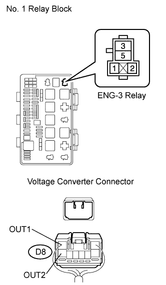
Remove the ENG-3 relay from the No. 1 relay block.
-
Disconnect the voltage converter connector.
-
Measure the resistance according to the value(s) in the table below.
Standard resistance Check for open Tester Connection Condition Specified Condition ENG-3 relay terminal 5 - D8-2 (OUT1) Always Below 1 Ω ENG-3 relay terminal 5 - D8-8 (OUT2) Always Below 1 Ω Check for short Tester Connection Condition Specified Condition ENG-3 relay terminal 5 or D8-2 (OUT1) - Body ground Always 10 kΩ or higher ENG-3 relay terminal 5 or D8-8 (OUT2) - Body ground Always 10 kΩ or higher -
Reinstall the ENG-3 relay.
-
Reconnect the voltage converter connector.
NG
REPAIR OR REPLACE HARNESS OR CONNECTOR (ENG-3 RELAY - VOLTAGE CONVERTER)
OK
CHECK VOLTAGE CONVERTER SYSTEM
-
-
CHECK ECM (IGSW VOLTAGE)
-
Turn the ignition switch to the ON position.
-
Measure the voltage according to the value(s) in the table below.
Standard voltage Tester Connection Condition Specified Condition E25-16 (IGSW) - Body ground Ignition switch in the ON position 11 to 14 V
NG
CHECK ENG-2 RELAY (VOLTAGE) Click here
OK
REPLACE ECM
-
-
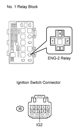
CHECK ENG-2 RELAY (VOLTAGE)
-
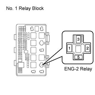
Remove the ENG-2 relay from the No. 1 relay block.
-
Turn the ignition switch to the ON position.
-
Measure the voltage according to the value(s) in the table below.
Standard voltage Tester Connection Condition Specified Condition ENG-2 relay terminal 1 - Body ground Ignition switch in the ON position 11 to 14 V -
Reinstall the ENG-2 relay.
NG
INSPECT FUSE (AM2 FUSE) Click here
OK
-
-
INSPECT FUSE (ENG FUSE)
-
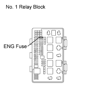
Remove the ENG fuse from the No. 1 relay block.
-
Measure the resistance according to the value(s) in the table below.
Standard resistance Tester Connection Condition Specified Condition 1 - 2 Always Below 1 Ω -
Reinstall the ENG fuse.
NG
REPLACE FUSE (ENG FUSE)
OK
-
-
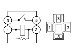
INSPECT ENG-2 RELAY
-
Remove the ENG-2 relay from the No. 1 relay block.
-
Measure the resistance according to the value(s) in the table below.
Standard resistance Tester Connection Condition Specified Condition 3 - 5 Always 10 kΩ or higher 3 - 5 Always below 1 Ω
(when battery voltage is applied to terminals 1 and 2)
-
Reinstall the ENG-2 relay.
NG
REPLACE ENG-2 RELAY
OK
-
-
CHECK HARNESS AND CONNECTOR (ENG-2 RELAY - ECM)
-
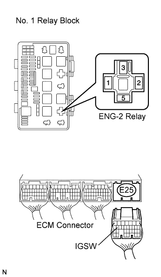
Remove the ENG-2 relay from the No. 1 relay block.
-
Disconnect the ECM connector.
-
Measure the resistance according to the value(s) in the table below.
Standard resistance Check for open Tester Connection Condition Specified Condition ENG-2 relay terminal 5 - E25-16 (IGSW) Always Below 1 Ω Check for short Tester Connection Condition Specified Condition ENG-2 relay terminal 5 or E25-16 (IGSW) - Body ground Always 10 kΩ or higher -
Reinstall the ENG-2 relay.
-
Reconnect the ECM connector.
NG
REPAIR OR REPLACE HARNESS OR CONNECTOR (ENG-2 RELAY - ECM)
OK
-
-
CHECK HARNESS AND CONNECTOR (ENG-2 RELAY - VOLTAGE CONVERTER)
-
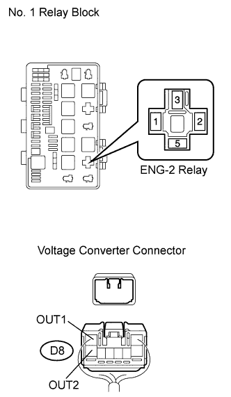
Remove the ENG-2 relay from the No. 1 relay block.
-
Disconnect the voltage converter connector.
-
Measure the resistance according to the value(s) in the table below.
Standard resistance Check for open Tester Connection Condition Specified Condition ENG-2 relay terminal 3 - D8-2 (OUT1) Always Below 1 Ω ENG-2 relay terminal 3 - D8-8 (OUT2) Always Below 1 Ω Check for short Tester Connection Condition Specified Condition ENG-2 relay terminal 3 or D8-2 (OUT1) - Body ground Always 10 kΩ or higher ENG-2 relay terminal 3 or D8-8 (OUT2) - Body ground Always 10 kΩ or higher -
Reinstall the ENG-2 relay.
-
Reconnect the voltage converter connector.
NG
REPAIR OR REPLACE HARNESS OR CONNECTOR (ENG-2 RELAY - VOLTAGE CONVERTER)
OK
-
-
CHECK HARNESS AND CONNECTOR (ENG-2 RELAY - BODY GROUND)
-
Remove the ENG-2 relay from the No. 1 relay block.
-
Measure the resistance according to the value(s) in the table below.
Standard resistance Tester Connection Condition Specified Condition ENG-2 relay terminal 2 - Body ground Always Below 1 Ω -
Reinstall the ENG-2 relay.
NG
REPAIR OR REPLACE HARNESS OR CONNECTOR (ENG-2 RELAY - BODY GROUND)
OK
CHECK VOLTAGE CONVERTER SYSTEM
-
-
INSPECT FUSE (AM2 FUSE)
-
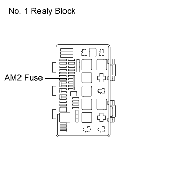
Remove the AM2 fuse from the No. 1 relay block.
-
Measure the resistance according to the value(s) in the table below.
Standard resistance Tester Connection Condition Specified Condition 1 - 2 Always Below 1 Ω -
Reinstall the AM2 fuse.
NG
REPLACE FUSE (AM2 FUSE)
OK
-
-
INSPECT IGNITION SWITCH ASSEMBLY
-
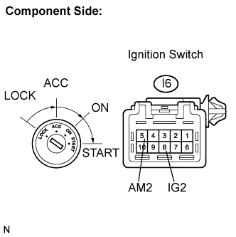
Disconnect the ignition switch connector.
-
Measure the resistance according to the value(s) in the table below.
Standard resistance Tester Connection Condition Specified Condition I6-5 (AM2) - I6-8 (IG2) LOCK 10 kΩ or higher I6-5 (AM2) - I6-8 (IG2) ON Below 1 Ω -
Reconnect the ignition switch connector.
NG
REPLACE IGNITION SWITCH ASSEMBLY
OK
-
-
CHECK HARNESS AND CONNECTOR (ENG-2 RELAY - IGNITION SWITCH)
-
Remove the ENG-2 relay from the No. 1 relay block.
-
Disconnect the ignition switch connector.
-
Measure the resistance according to the value(s) in the table below.
Standard resistance Check for open Tester Connection Condition Specified Condition ENG-2 relay terminal 1 - I6-8 (IG2) Always Below 1 Ω Check for short Tester Connection Condition Specified Condition ENG-2 relay terminal 1 or I6-8 (IG2) - Body ground Always 10 kΩ or higher -
Reinstall the ENG-2 relay.
-
Reconnect the ignition switch connector.
NG
REPAIR OR REPLACE HARNESS OR CONNECTOR (ENG-2 RELAY - IGNITION SWITCH)
OK
REPAIR OR REPLACE HARNESS OR CONNECTOR (IGNITION SWITCH - BATTERY)
-