ECD SYSTEM, Diagnostic DTC:P0500

| DTC Code | DTC Name |
|---|---|
| P0500 | Vehicle Speed Sensor "A" |
DESCRIPTION
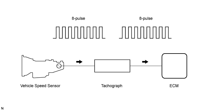
The vehicle speed sensor outputs on 8-pulse signal every revolution of the rotor shaft, which is rotated by the transmission output shaft via the driven gear. After this signal is converted into a more precise rectangular waveform by the waveform shaping circuit inside the tachograph, it is then transmitted to the ECM. The ECM determines the vehicle speed, based on the frequency of these pulse signals.
| DTC No. | DTC Detection Condition | Trouble Area |
|---|---|---|
| P0500 | All conditions below are detected continuously for 8 seconds or more: (a) Vehicle speed signal is 0 km/h (0 mph) (b) Engine speed: 1500 to 2500 rpm (c) Engine coolant temp. is 70°C (158°F) or more (d) ECT sensor, accelerator pedal position sensor, and MAF meter are all normal |
|
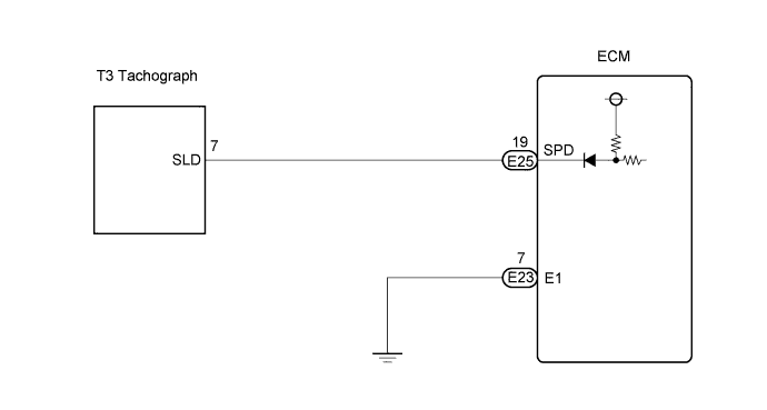
WIRING DIAGRAM
INSPECTION PROCEDURE
Tech Tips
Read freeze frame data using the intelligent tester. The ECM records vehicle and driving condition information as freeze frame data the moment a DTC is stored. When troubleshooting, freeze frame data can be helpful in determining whether the vehicle was running or stopped, whether the engine was warmed up or not, whether the air fuel ratio was lean or rich, as well as other data recorded at the time of a malfunction.
PROCEDURE
-
READ VALUE USING INTELLIGENT TESTER (VEHICLE SPEED)
-
Drive the vehicle and check whether the operation of the speedometer in the combination meter is normal.
Tech Tips
-
The vehicle speed sensor is operating normally if the speedometer reading is normal.
-
If the speedometer does not operate, check it by following the procedure described in speedometer malfunction.
-
NG 
CHECK ECM (SPD VOLTAGE) Click here
OK 
REPAIR OR REPLACE HARNESS OR CONNECTOR (TACHOGRAPH - ECM)
-
-
CHECK ECM (SPD VOLTAGE)
-
Drive the vehicle.
-
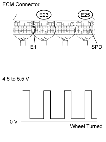
Measure the voltage between the terminals of the ECM connectors as the wheel is turned slowly.
Standard voltage Tester Connection Specified Condition E25-19 (SPD) - E23-7 (E1) Generated intermittently Tech Tips
The output voltage should fluctuate up and down similarly to the diagram when the wheel is turned slowly.
NG
CHECK HARNESS AND CONNECTOR (TACHOGRAPH - ECM) Click here
OK
REPLACE ECM
-
-
CHECK HARNESS AND CONNECTOR (TACHOGRAPH - ECM)
-
Disconnect the tachograph connector.
-
Disconnect the ECM connector.
-
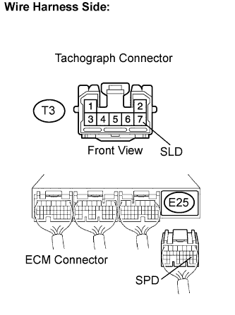
Measure the resistance according to the value(s) in the table below.
Standard resistance Check for open Tester Connection Condition Specified Condition E25-19 (SPD) - T3-7 (SLD) Always Below 1 Ω Check for short Tester Connection Condition Specified Condition E25-19 (SPD) or T3-7 (SLD) - Body ground Always 10 kΩ or higher
NG 
CHECK FOR INTERMITTENT PROBLEMS
OK
CHECK TACHOGRAPH SYSTEM
-