ECD SYSTEM Black Smoke Emitted
INSPECTION PROCEDURE
Note
-
After replacing the ECM, the new ECM needs registration Click here and initialization Click here.
-
After replacing the supply pump, the ECM needs initialization Click here.
-
After replacing an injector, the ECM needs registration Click here.
Tech Tips
Specified values in the following troubleshooting flowchart are for reference only. Variations in the Data List values may occur depending on the measuring conditions or the vehicle's age. Do not assume the vehicle to be normal when the Data List outputs standard values. There may be concealed factors causing the malfunction.
PROCEDURE
-
CHECK OUTPUT DTC (RELATED TO ENGINE)
-
Connect the intelligent tester to the DLC3.
-
Turn the ignition switch to the ON position.
-
Turn the tester on.
-
Enter the following menu items: Powertrain / Engine and ECT / DTC.
-
Read the DTCs.
Result Display (DTC Output) Proceed to No output A DTCs related to the engine B
B 
GO TO DTC CHART
A 
-
-
READ VALUE USING INJECTOR ASSEMBLY (INJECTION VOLUME AND INJECTION FEED BACK VAL #1 TO #4)
-
Connect the intelligent tester to the DLC3.
-
Start the engine.
-
Turn the tester on.
-
Enter the following menu items: Powertrain / Engine and ECT / Data List.
-
Select the following menu items in order and read the values.
-
Injection Volume
-
Injection Feedback Val #1, #2, #3, and #4
Standard Item Engine Speed* Reference Value Injection Volume Idling (No engine load) 5 to 12 mm3
Injection Feedback Val #1 Idling (No engine load) -3.0 to 3.0 mm3
Injection Feedback Val #2 Idling (No engine load) -3.0 to 3.0 mm3
Injection Feedback Val #3 Idling (No engine load) -3.0 to 3.0 mm3
Injection Feedback Val #4 Idling (No engine load) -3.0 to 3.0 mm3
Tech Tips
*: If no idling conditions are specified, the shift lever should be in the neutral position, and the A/C switch and all accessory switches should be off.
-
NG 
CHECK ECM TERMINAL VOLTAGE (THW TERMINAL) Click here
OK
-
-
PERFORM ENGINE RPM ACCELERATION
Tech Tips
If the exhaust gas contains excessive black smoke, perform the following operations:
-
Accelerate the engine speed to the maximum rpm with no load 20 times.
-
Check for black smoke in the exhaust gas.
Result Result Proceed to Black smoke is not present OK Black smoke remains in the exhaust gas NG Tech Tips
Soot deposits in the exhaust system may cause excessive black smoke.
NG
CHECK AIR INTAKE SYSTEM AND EXHAUST SYSTEM Click here
OK 
END
-
-
CHECK AIR INTAKE SYSTEM AND EXHAUST SYSTEM
-
Inspect the engine condition Click here.
NG
CHECK AND REPLACE LOCATIONS WHERE MALFUNCTIONS EXIST
OK
-
-
INSPECT EXHAUST RETARDER ASSEMBLY
-
Inspect the exhaust retarder assembly.
NG
REPLACE EXHAUST RETARDER ASSEMBLY
OK
-
-
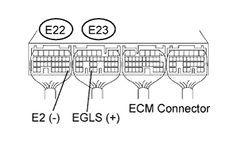
CHECK ECM TERMINAL VOLTAGE (EGLS TERMINAL)
Tech Tips
The lifting amount of the EGR valve can be checked using the output of the EGR position sensor.
-
Start the engine.
-
Measure the voltage according to the value(s) in the table below.
Standard voltage Tester Connection Condition Specified Condition E23-33 (EGLS) - E22-28 (E2) Engine: Idling 2.7 to 3.0 V E23-33 (EGLS) - E22-28 (E2) Engine: 3000 rpm 3.3 to 3.6 V Tech Tips
In the chart above, "Idling" means that the engine should be idled under the following conditions:
-
The A/C switch is off and the shift lever is in the neutral position.
-
After the engine is warmed up, the engine should have no load.
-
NG
REPLACE EGR VALVE ASSEMBLY
OK
-
-
CHECK TURBOCHARGER SUB-ASSEMBLY (PRESSURE)
-
Check the turbocharger pressure Click here.
NG
REPLACE TURBOCHARGER SUB-ASSEMBLY
OK
-
-
PERFORM ACTIVE TEST USING FUEL PRESSURE SENSOR AND INJECTOR ASSEMBLY
-
Connect the intelligent tester to the DLC3.
-
Start the engine and turn the intelligent tester on.
-
Enter the following menu items: Powertrain / Engine and ECT / Data List.
-
Select the following menu items in order and read the values.
-
Fuel Press
-
Injection Volume
-
Main Injection Period
-
Pilot 2 Injection Period
-
Injection Feedback Val #1, #2, #3, and #4
Result Item Engine Speed* Reference Value Fuel Pressure Idling 25 to 35 MPa Fuel Pressure 2,000 rpm (no engine load) 80 to 90 MPa Fuel Pressure 3,000 rpm (no engine load) 100 to 110 MPa Injection Volume Idling 5.0 to 12.0 mm3
Injection Volume 2,000 rpm (no engine load) 8.0 to 15.0 mm3
Injection Volume 3,000 rpm (no engine load) 13.0 to 20.0 mm3
Main Injection Period Idling 500 to 700 μs Pilot 2 Injection Period Idling 500 to 600 μs Injection Feedback Val #1 Idling -3.0 to 3.0 mm3
Injection Feedback Val #2 Idling -3.0 to 3.0 mm3
Injection Feedback Val #3 Idling -3.0 to 3.0 mm3
Injection Feedback Val #4 Idling -3.0 to 3.0 mm3
Tech Tips
If no idling conditions are specified, the shift lever should be in the neutral position, and the A/C switch and all accessory switches should be off.
Result Result Proceed to Within reference value A One of Injection Feedback Val #1 to #4 is not within reference value B Other result C -
B
REPLACE INJECTOR ASSEMBLY
C
CHECK ECM TERMINAL VOLTAGE (THW TERMINAL) Click here
A
-
-
CHECK CYLINDER COMPRESSION PRESSURE
-
Check the cylinder compression pressure Click here.
NG
CHECK ENGINE TO DETERMINE CAUSE OF LOW COMPRESSION
OK
-
-
CHECK HARNESS AND CONNECTOR (INJECTOR ASSEMBLY - EDU)
-
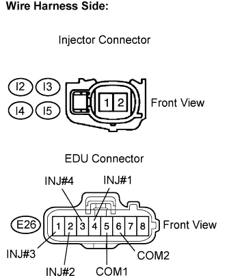
Disconnect the injector connectors.
-
Disconnect the EDU connector.
-
Measure the resistance according to the value(s) in the table below.
Standard resistance Check for open Tester Connection Condition Specified Condition I2-2 - E26-4 (INJ#1) Always Below 1 Ω I3-2 - E26-2 (INJ#2) Always Below 1 Ω I4-2 - E26-1 (INJ#3) Always Below 1 Ω I5-2 - E26-3 (INJ#4) Always Below 1 Ω I2-1 - E26-5 (COM1) Always Below 1 Ω I3-1 - E26-6 (COM2) Always Below 1 Ω I4-1 - E26-6 (COM2) Always Below 1 Ω I5-1 - E26-5 (COM1) Always Below 1 Ω Check for short Tester Connection Condition Specified Condition I2-2 or E26-4 (INJ#1) - Body ground Always 10 kΩ or higher I3-2 or E26-2 (INJ#2) - Body ground Always 10 kΩ or higher I4-2 or E26-1 (INJ#3) - Body ground Always 10 kΩ or higher I5-2 or E26-3 (INJ#4) - Body ground Always 10 kΩ or higher I2-1 or E26-5 (COM1) - Body ground Always 10 kΩ or higher I3-1 or E26-6 (COM2) - Body ground Always 10 kΩ or higher I4-1 or E26-6 (COM2) - Body ground Always 10 kΩ or higher I5-1 or E26-5 (COM1) - Body ground Always 10 kΩ or higher -
Reconnect the EDU connector.
-
Reconnect the injector connectors.
NG
REPAIR OR REPLACE HARNESS OR CONNECTOR (INJECTOR ASSEMBLY - EDU)
OK
-
-
INSPECT INJECTOR ASSEMBLY
-
Start the engine.
-
Disconnect the connectors for the No. 1 through No. 4 injectors in this order.
-
Check the engine idling condition during fuel injection of each cylinder.
Result Engine Idling Condition Proceed to Becomes unstable A Does not change B Tech Tips
Replace the injector mounted on the cylinder that causes no significant idle speed change.
-
Clear the DTCs Click here.
B
REPLACE INJECTOR ASSEMBLY
A
REPLACE EDU
-
-
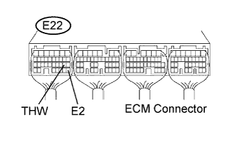
CHECK ECM TERMINAL VOLTAGE (THW TERMINAL)
-
Start the engine.
-
Measure the voltage according to the value(s) in the table below.
Standard voltage Tester Connection Condition Specified Condition E22-19 (THW) - E22-28 (E2) Idling, engine coolant temperature between 80 and 120°C (176 and 248°F) 0.4 to 1.0 V
NG
INSPECT ENGINE COOLANT TEMPERATURE SENSOR Click here
OK
-
-
CHECK ECM TERMINAL VOLTAGE (PIM TERMINAL)
-

Turn the ignition switch to the ON position.
-
Measure the voltage according to the value(s) in the table below.
Standard voltage Tester Connection Condition Specified Condition E23-28 (PIM) - E22-28 (E2) Applied negative pressure of 93 kPa (700 mmHg, 27.5 in.Hg) 0.25 to 0.4 V E23-28 (PIM) - E22-28 (E2) Applied positive pressure of 150 kPa (1125 mmHg, 44 in.Hg) 1.0 to 1.4 V
NG
CHECK HARNESS AND CONNECTOR (TURBO PRESSURE SENSOR - ECM) Click here
OK
-
-
CHECK ECM TERMINAL VOLTAGE (NE+ AND NE- TERMINALS)
-
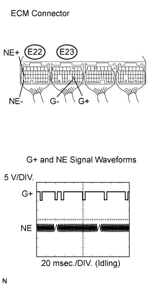
While idling the engine, check the waveform of the ECM connector using an oscilloscope.
Standard Tester Connection Specified Condition E22-27 (NE+) - E22-34 (NE-) Correct waveform appears as shown Tool Setting 5 V/DIV., 20 msec./DIV. Condition Idling with warm engine Tech Tips
The waveform varies depending on engine revolution.
NG
INSPECT CRANKSHAFT POSITION SENSOR Click here
OK
-
-
CHECK ECM TERMINAL VOLTAGE (VPA AND VPA2 TERMINALS)
-
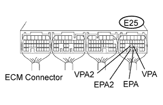
Turn the ignition switch to the ON position.
-
Measure the voltage according to the value(s) in the table below.
Standard voltage Tester Condition Accelerator Pedal Condition Specified Condition E25-22 (VPA) - E25-28 (EPA) Released 0.6 to 1.0 V E25-22 (VPA) - E25-28 (EPA) Depressed 2.8 to 3.6 V E25-23 (VPA2) - E25-29 (EPA2) Released 1.4 to 1.8 V E25-23 (VPA2) - E25-29 (EPA2) Depressed 3.6 to 4.4 V
NG
CHECK HARNESS AND CONNECTOR (ACCELERATOR PEDAL POSITION SENSOR - ECM) Click here
OK
-
-
CHECK ECM TERMINAL VOLTAGE (THA TERMINAL)
-
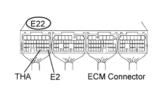
Start the engine.
-
Measure the voltage according to the value(s) in the table below.
Standard voltage Tester Connection Condition Specified Condition E22-31 (THA) - E22-28 (E2) Idling, intake air temperature at 20°C (68°F) 0.5 to 3.4 V
NG
INSPECT INTAKE AIR TEMPERATURE SENSOR Click here
OK
-
-
CHECK ECM TERMINAL VOLTAGE (PCR1 TERMINAL)
-
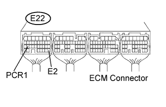
Start the engine.
-
Measure the voltage according to the value(s) in the table below.
Standard voltage Tester Connection Condition Specified Condition E22-26 (PCR1) - E22-28 (E2) Idling 1.7 to 2.2 V
NG
INSPECT COMMON RAIL ASSEMBLY (FUEL PRESSURE SENSOR) Click here
OK
REPLACE ECM
-
-
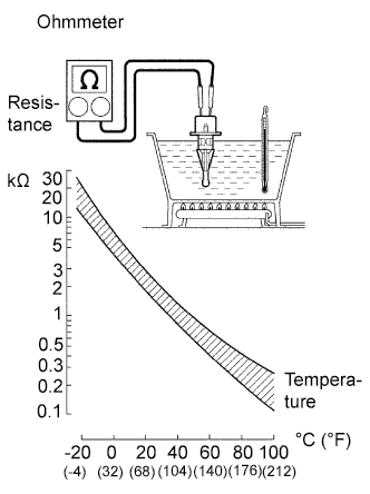
INSPECT ENGINE COOLANT TEMPERATURE SENSOR
-
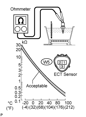
Remove the engine coolant temperature sensor.
-
Measure the resistance according to the value(s) in the table below.
Standard resistance Tester Connection Condition Specified Condition W5-1 - W5-2 20°C (68°F) 2.32 to 2.59 kΩ W5-1 - W5-2 80°C (176°F) 0.31 to 0.326 kΩ Note
When checking the ECT sensor in water, keep the terminals dry. After the check, wipe the sensor dry.
Tech Tips
Alternative procedure: Connect an ohmmeter to the installed ECT sensor and read the resistance. Use an infrared thermometer to measure the engine temperature in the immediate vicinity of the sensor. Compare these values against the resistance/ temperature graph. Change the engine temperature (warm up or cool down) and repeat the test.
-
Reinstall the engine coolant temperature sensor.
NG
REPLACE ENGINE COOLANT TEMPERATURE SENSOR
OK
REPAIR OR REPLACE HARNESS OR CONNECTOR (INJECTOR ASSEMBLY - EDU)
-
-
CHECK HARNESS AND CONNECTOR (TURBO PRESSURE SENSOR - ECM)
-
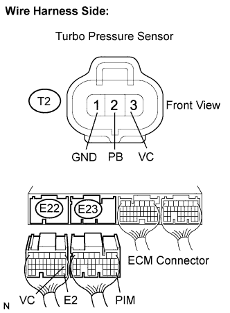
Disconnect the turbo pressure sensor connector.
-
Disconnect the ECM connectors.
-
Measure the resistance according to the value(s) in the table below.
Standard resistance Check for open Tester Connection Condition Specified Condition E23-28 (PIM) - T2-2 (PB) Always Below 1 Ω E22-18 (VC) - T2-3 (VC) Always Below 1 Ω E22-28 (E2) - T2-1 (GND) Always Below 1 Ω Check for short Tester Connection Condition Specified Condition E23-28 (PIM) or T2-2 (PB) - Body ground Always 10 kΩ or higher E22-18 (VC) or T2-3 (VC) - Body ground Always 10 kΩ or higher E22-28 (E2) or T2-1 (GND) - Body ground Always 10 kΩ or higher -
Reconnect the turbo pressure sensor.
-
Reconnect the ECM connectors.
NG
REPAIR OR REPLACE HARNESS OR CONNECTOR (TURBO PRESSURE SENSOR - ECM)
OK
REPLACE TURBO PRESSURE SENSOR
-
-
INSPECT CRANKSHAFT POSITION SENSOR
-
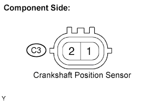
Disconnect the crankshaft position sensor connector.
-
Measure the resistance according to the value(s) in the table below.
Standard resistance Tester Connection Condition Specified Condition C3-1 - C3-2 Cold 1630 to 2740 Ω C3-1 - C3-2 Hot 2065 to 3225 Ω Note
In the table above, the terms "cold" and "hot" refer to the temperature of the coils in the sensors. "Cold" means approximately -10 to 50°C (14 to 122°F). "Hot" means approximately 50 to 100°C (122 to 212°F).
NG
REPLACE CRANKSHAFT POSITION SENSOR
OK
REPAIR OR REPLACE HARNESS OR CONNECTOR (CRANKSHAFT POSITION SENSOR - ECM)
-
-
CHECK HARNESS AND CONNECTOR (ACCELERATOR PEDAL POSITION SENSOR - ECM)
-
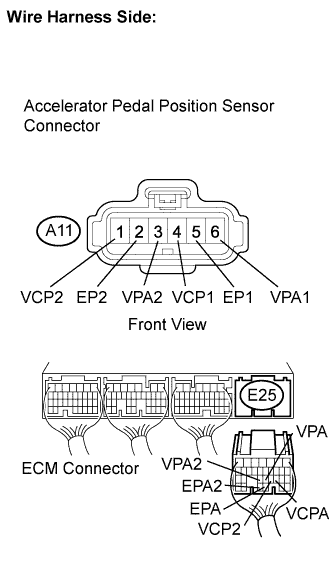
Disconnect the accelerator pedal position sensor connector.
-
Disconnect the ECM connector.
-
Measure the resistance according to the value(s) in the table below.
Standard resistance Check for open Tester Connection Condition Specified Condition A11-1 (VCP2) - E25-21 (VCP2) Always Below 1 Ω A11-2 (EP2) - E25-29 (EPA2) Always Below 1 Ω A11-3 (VPA2) - E25-23 (VPA2) Always Below 1 Ω A11-4 (VCP1) - E25-20 (VCPA) Always Below 1 Ω A11-5 (EP1) - E25-28 (EPA) Always Below 1 Ω A11-6 (VPA1) - E25-22 (VPA) Always Below 1 Ω Check for short Tester Connection Condition Specified Condition A11-1 (VCP2) or E25-21 (VCP2) - Body ground Always 10 kΩ or higher A11-2 (EP2) or E25-29 (EPA2) - Body ground Always 10 kΩ or higher A11-3 (VPA2) or E25-23 (VPA2) - Body ground Always 10 kΩ or higher A11-4 (VCP1) or E25-20 (VCPA) - Body ground Always 10 kΩ or higher A11-5 (EP1) or E25-28 (EPA) - Body ground Always 10 kΩ or higher A11-6 (VPA1) or E25-22 (VPA) - Body ground Always 10 kΩ or higher -
Reconnect the accelerator pedal position sensor connector.
-
Reconnect the ECM connector.
NG
REPAIR OR REPLACE HARNESS OR CONNECTOR (ACCELERATOR PEDAL POSITION SENSOR - ECM)
OK
REPLACE ACCELERATOR PEDAL (ACCELERATOR PEDAL POSITION SENSOR)
-
-
INSPECT INTAKE AIR TEMPERATURE SENSOR
-
Remove the intake air temperature sensor.
-
Measure the resistance according to the value(s) in the table below.
Standard resistance Tester Connection Condition Specified Condition I9-1 - I9-2 20°C (68°F) 2.21 to 2.65 kΩ I9-1 - I9-2 60°C (140°F) 0.55 to 0.61 kΩ Note
When checking the sensor in water, keep the terminals dry. After the check, wipe the sensor dry.
NG
REPLACE INTAKE AIR TEMPERATURE SENSOR
OK
REPAIR OR REPLACE HARNESS OR CONNECTOR (INTAKE AIR TEMPERATURE SENSOR - ECM)
-
-
INSPECT COMMON RAIL ASSEMBLY (FUEL PRESSURE SENSOR)
-
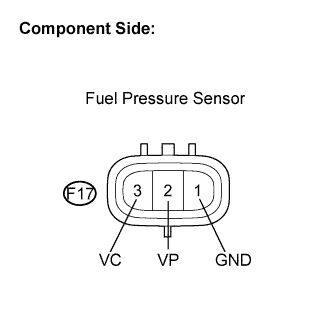
Disconnect the fuel pressure sensor connector.
-
Measure the resistance according to the value(s) in the table below.
Standard resistance Tester Connection Specified Condition F17-2 (VP) - F17-1 (GND) 16.4 kΩ or less F17-3 (VC) - F17-2 (VP) 3 kΩ or less -
Reconnect the fuel pressure sensor connector.
NG
REPLACE COMMON RAIL ASSEMBLY
OK
-
-
CHECK HARNESS AND CONNECTOR (FUEL PRESSURE SENSOR - ECM)
-
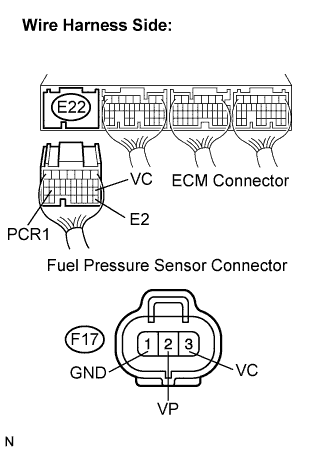
Disconnect the ECM connectors.
-
Disconnect the fuel pressure sensor connector.
-
Measure the resistance according to the value(s) in the table below.
Standard resistance Check for open Tester Connection Condition Specified Condition E22-26 (PCR1) - F17-2 (VP) Always Below 1 Ω E22-18 (VC) - F17-3 (VC) Always Below 1 Ω E22-28 (E2) - F17-1 (GND) Always Below 1 Ω Check for short Tester Connection Condition Specified Condition E22-26 (PCR1) or F17-2 (VP) - Body ground Always 10 kΩ or higher E22-18 (VC) or F17-3 (VC) - Body ground Always 10 kΩ or higher E22-28 (E2) or F17-1 (GND) - Body ground Always 10 kΩ or higher -
Reconnect the ECM connector.
-
Reconnect the fuel pressure sensor connector.
NG
REPAIR OR REPLACE HARNESS OR CONNECTOR (INJECTOR ASSEMBLY - EDU)
OK
-
-
REPLACE ECM
-
Replace the ECM.
Note
After replacing the ECM, the new ECM needs registration Click here and initialization Click here.
-
Check the volume of black smoke in the exhaust gas.
OK Black smoke is not present.
NG
REPLACE SUPPLY PUMP ASSEMBLY
OK
END
-