ECD SYSTEM FREEZE FRAME DATA

-
DESCRIPTION
-
The ECM records vehicle and driving condition information as freeze frame data the moment a DTC is stored. When troubleshooting, freeze frame data can be helpful in determining whether the vehicle was running or stopped, whether the air fuel ratio was lean or rich, as well as other data recorded at the time of a malfunction.
Tech Tips
If it is impossible to duplicate the problem even though a DTC is detected, confirm the freeze frame data.
-
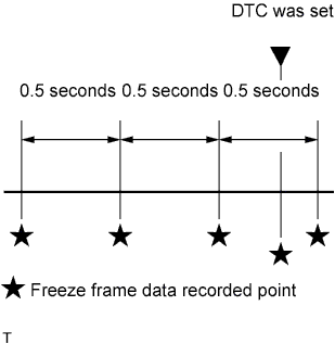
The ECM records engine conditions in the form of freeze frame data every 0.5 seconds. Using an intelligent tester, 5 separate sets of freeze frame data can be checked.
-
3 data sets before the DTC was set.
-
1 data set when the DTC was set.
-
1 data set after the DTC was set.
-
These data sets can be used to simulate the condition of the vehicle around the time of the occurrence of the malfunction. The data may assist in identifying the cause of the malfunction, and in judging whether it was temporary or not.
-
-
LIST OF FREEZE FRAME DATA
LABEL
(Tester Display)
Measurement Item/Range Diagnostic Note Trouble Code Freeze DTC - Calculate Load Calculated load Calculated load by ECM MAF Mass air flow volume If approximately 0.0 g/sec.:
-
Mass air flow meter power source circuit is open or shorted
-
VG circuit is open or shorted
If 160.0 g/sec. or more:
-
E2G circuit is open
MAP Absolute pressure inside intake manifold - Engine Speed Engine speed - Vehicle Speed Vehicle speed Speed indicated on speedometer Coolant Temp Engine coolant temperature If -40°C (-40°F), sensor circuit is open
If 140°C (284°F) or more, sensor circuit is shorted
Intake Air Intake air temperature If -40°C (-40°F), sensor circuit is open
If 140°C (284°F) or more, sensor circuit is shorted
Fuel Press Fuel pressure - Target EGR Position Target EGR position - Accelerator Position No. 1 Absolute accelerator pedal position No. 1 - Accelerator Position No. 2 Absolute accelerator pedal position No. 2 - Throttle Motor Duty Throttle actuator duty - Initial Engine Coolant Temp Engine coolant temperature at engine start - Initial Intake Air Temp Intake air temperature at engine start - Exhaust Temp (In) Exhaust temperature sensor for IN - Exhaust Temp (Out) Exhaust temperature sensor for OUT - Intake Air Temp (Turbo) Intake air temperature (Turbo) - DPF Differential Pressure DPF differential pressure - EGR Lift Sensor Output EGR lift position - EGR Close Lrn. Val EGR close learning value - Accel Position Accelerator pedal position sensor - Fuel Temperature Fuel temperature - VNT Command VN turbo command - Target Pump SCV Current Target suction control valve current - Inj. FB Vol. for Idle Idle stable control - Actual Throttle Position Actual throttle position - Pilot 1 Injection Period Pilot 1 injection period - Pilot 2 Injection Period Pilot 2 injection period - Main Injection Period Main injection period - After Injection Period After injection period - Pilot 1 Injection Timing Pilot 1 injection timing - Pilot 2 Injection Timing Pilot 2 injection timing - Main Injection Timing Main injection timing - After Injection Timing After injection timing - Inj Vol Feedback Leaning Injection volume feedback learning value - Injection Feedback Val #1 Injection volume correction for cylinder 1 - Injection Feedback Val #2 Injection volume correction for cylinder 2 - Injection Feedback Val #3 Injection volume correction for cylinder 3 - Injection Feedback Val #4 Injection volume correction for cylinder 4 - Injection Volume Injection volume - Diesel Throttle Lean Status Diesel throttle leaning status - EGR Close Lrn. Status EGR close leaning status - Starter Signal Starter switch signal - A/C Signal Air conditioning signal - Stop Light Switch Stop light switch - Catalyst Regeneration Switch Catalyst regeneration switch status - Exhaust Brake Switch Exhaust brake switch status - PTO Switch PTO switch status - Clutch Switch Clutch switch status - Engine Warm Up Switch Engine warm up switch status - Battery Voltage Battery voltage - Atmosphere Pressure Atmosphere pressure - ACT VSV ACT VSV status TC and TE1 TC and TE1 terminals of DLC3 - Engine Run Time Accumulated engine running time - Time after DTC Cleared Cumulative time after DTC cleared - Distance from DTC Cleared Accumulated distance after DTC cleared - Warmup Cycle Cleared DTC Warm-up cycle after DTC cleared - -