ECD SYSTEM DIAGNOSIS SYSTEM

-
DESCRIPTION

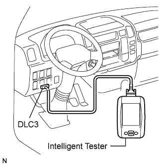
When troubleshooting Euro-OBD vehicles, the vehicle must be connected to the intelligent tester. Various data output from the vehicle's Engine Control Module (ECM) can then be read.
The Malfunction Indicator Lamp (MIL) is illuminated and blinked when the vehicle's on-board computer detects a malfunction in the computer itself or in drive system components. In addition, the applicable Diagnostic Trouble Codes (DTCs) are recorded in the ECM memory Click here.
If the malfunction does not recur, the MIL stays ON until the ignition switch is turned off, and then the MIL turns off when the ignition switch is turned to the ON position. Be aware that the DTCs remain recorded in the ECM memory.
To check the DTCs, connect the intelligent tester to the DLC3 on the vehicle.
-
NORMAL MODE AND CHECK MODE
The diagnosis system operates in "normal mode" during normal vehicle use. In normal mode, "2 trip detection logic" is used to ensure accurate detection of malfunctions. "Check mode" is also available to technicians as an option. In check mode, "1 trip detection logic" is used for simulating malfunction symptoms and increasing the system's ability to detect malfunctions, including intermittent malfunctions Click here.
-
2 TRIP DETECTION LOGIC
When a malfunction is first detected, the malfunction is temporarily stored in the ECM memory (1st trip). If the same malfunction is detected during the next subsequent drive cycle, the MIL is illuminated (2nd trip).
-
FREEZE FRAME DATA
The ECM records vehicle and driving condition information as freeze frame data the moment a DTC is stored. When troubleshooting, freeze frame data can be helpful in determining whether the vehicle was running or stopped, whether the engine was warmed up or not, whether the air fuel ratio was lean or rich, as well as other data recorded at the time of a malfunction.
-
DLC3 (Data Link Connector 3)
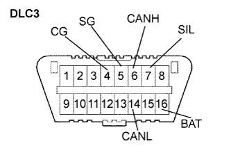
The vehicle's ECM uses ISO 15765-4 for communication protocol. The terminal arrangement of the DLC3 complies with ISO 15031-03 and matches the ISO 15765-4 format.
Tech Tips
Connect the cable of the intelligent tester to the DLC3, turn the ignition switch to the ON position and attempt to use the tester. If the display indicates that a communication error has occurred, there is a problem either with the vehicle or with the tester.
If communication is normal when the tester is connected to another vehicle, inspect the DLC3 of the original vehicle.
If communication is still not possible when the tester is connected to another vehicle, the problem may be in the tester itself. Consult the Service Department listed in the tester's instruction manual.
Symbols (Terminal No.) Terminal Description Condition Result SIL (7) - SG (5) Bus "+" line During transmission Pulse generation CG (4) - Body ground Chassis ground Always Below 1 Ω SG (5) - Body ground Signal ground Always Below 1 Ω BAT (16) - Body ground Battery positive Always 18 to 27 V CANH (6) - CANL (14) CAN bus line Ignition switch off* 54 to 69 Ω CANH (6) - CG (4) HIGH-level CAN bus line Ignition switch off* 200 Ω or higher CANL (14) - CG (4) LOW-level CAN bus line Ignition switch off* 200 Ω or higher CANH (6) - BAT (16) HIGH-level CAN bus line Ignition switch off* 6 kΩ or higher CANL (14) - BAT (16) LOW-level CAN bus line Ignition switch off* 6 kΩ or higher Note
-
*: Before measuring the resistance, leave the vehicle as is for at least 1 minute and do not operate the ignition switch, any other switches or the doors.
Tech Tips
Connect the cable of an intelligent tester to the DLC3, turn the ignition switch to the ON position and attempt to use the tester. If the display indicates that a communication error has occurred, there is a problem either with the vehicle or with the tester.
If communication is normal when the tester is connected to another vehicle, inspect the DLC3 of the original vehicle.
If communication is still not possible when the tester is connected to another vehicle, the problem may be in the tester itself. Consult the Service Department listed in the tester's instruction manual.
-
-
INSPECT BATTERY VOLTAGE
If the voltage is below 18 V, recharge or replace the battery before proceeding to the next step.
-
CHECK MIL
-
The MIL will be illuminated when the ignition switch is turned to the ON position and the engine is not running.
Tech Tips
If the MIL is not illuminated, check the MIL circuit Click here.
-
When the engine is started, the MIL should turn OFF. If the lamp remains ON or flashes, the diagnosis system has detected a malfunction or abnormality in the ECD system.
-
-
ALL READINESS
Tech Tips
-
With "All Readiness" you can check whether or not the DTC judgement has been completed by using the intelligent tester.
-
You should check "All Readiness" after simulating malfunction symptoms or for validation after finishing repairs.
-
Connect the intelligent tester to the DLC3.
-
Turn the ignition switch to the ON position.
-
Turn the tester on.
-
Clear the DTCs Click here.
-
Perform the DTC judgment driving pattern to run the DTC judgement.
-
Enter the following menus: Powertrain / Engine and ECT / Utility / All Readiness.
-
Input the DTCs to be confirmed.
-
Check the DTC judgement result.
Result Tester Display Description NORMAL
-
DTC judgement completed
-
System normal
ABNORMAL
-
DTC judgement completed
-
System abnormal
INCOMPLETE
-
DTC judgement not completed
-
You should perform driving after confirming DTC enabling conditions
UNKNOWN
-
Unable to perform DTC judgement
-
Number of DTCs which do not fulfill DTC preconditions has reached ECU's memory limit
-
-