ECD SYSTEM, Diagnostic DTC:P0045

| DTC Code | DTC Name |
|---|---|
| P0045 | Turbocharger / Supercharger Boost Control Solenoid Circuit / Open |
DESCRIPTION
The turbocharger system is comprised of the Variable Nozzle (VN) type turbocharger, the turbo motor driver and ECM.
The turbocharger has a nozzle vane which opens and closes to control the volume of the exhaust gas flowing into the turbine. This, in turn, controls the boost pressure. When the nozzle vane moves towards the closing direction, the pressure increases. When the vane moves towards the opening direction, the pressure decreases.
The turbocharger actuator built on the turbine side activates the nozzle vane. The nozzle vane position sensor built on the actuator detects the opening angle of the nozzle vane. The nozzle vane position sensor signal is sent via the turbo motor driver to the ECM. Then, based on the signal, the ECM actuates the actuator.
The ECM sends a target nozzle vane position signal to the turbo motor driver to obtain the nozzle vane position for the optimal boost pressure in accordance with the driving conditions.
| DTC No. | DTC Detection Condition | Trouble Area |
|---|---|---|
| P0045 | Send trouble signal in VN turbo controller for 0.3 seconds or more |
|
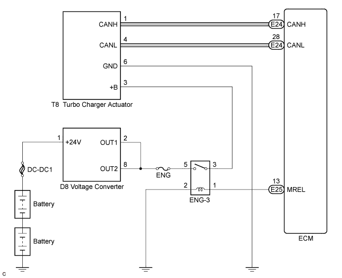
WIRING DIAGRAM
INSPECTION PROCEDURE
Tech Tips
Read freeze frame data using the intelligent tester. The ECM records vehicle and driving condition information as freeze frame data the moment a DTC is stored. When troubleshooting, freeze frame data can be helpful in determining whether the vehicle was running or stopped, whether the engine was warmed up or not, whether the air fuel ratio was lean or rich, as well as other data recorded at the time of a malfunction.
PROCEDURE
-
CHECK TURBOCHARGER (POWER SOURCE)
-
Disconnect the turbocharger actuator connector.
-
Turn the ignition switch to the ON position.
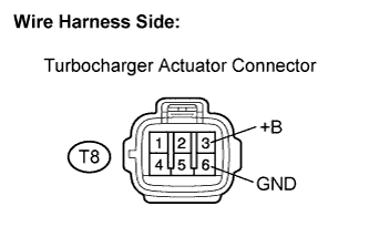
Measure the voltage according to the value(s) in the table below.
Standard voltage Tester Connection Condition Specified Condition T8-3 (+B) - T8-6 (GND) Ignition switch on 9 to 14 V
NG 
CHECK HARNESS OR CONNECTOR (TURBOCHARGER - BODY GROUND) Click here
OK 
-
-
INSPECT TURBOCHARGER SUB-ASSEMBLY
-
Inspect the turbocharger sub-assembly Click here.
NG 
REPLACE TURBOCHARGER SUB-ASSEMBLY
OK
-
-
REPLACE ECM
-
Replace the ECM Click here.
NEXT
-
-
CHECK WHETHER DTC OUTPUT RECURS
-
Connect the intelligent tester to the DLC3.
-
Turn the ignition switch to the ON position.
-
Turn the tester on.
-
Enter the following menu items: Powertrain / Engine and ECT / DTC.
-
Read the DTCs.
Result Display (DTC output) Proceed to No output A P0045 B
B
REPLACE TURBOCHARGER SUB-ASSEMBLY
A 
END
-
-
CHECK HARNESS OR CONNECTOR (TURBOCHARGER - BODY GROUND)
-
Disconnect the turbocharger actuator connector.
-
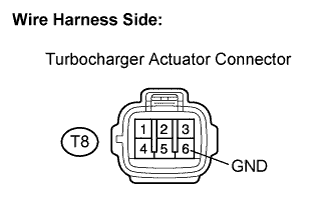
Measure the resistance according to the value(s) in the table below.
Standard resistance Tester Connection Condition Specified Condition T8-6 (GND) - Body ground Always Below 1 Ω -
Reconnect the turbocharger actuator connector.
NG
REPAIR OR REPLACE HARNESS OR CONNECTOR (TURBOCHARGER - BODY GROUND)
OK
REPAIR OR REPLACE HARNESS OR CONNECTOR (TURBOCHARGER - ENG-3 RELAY)
-