ECD SYSTEM, Diagnostic DTC:P1425, P1427, P1428

| DTC Code | DTC Name |
|---|---|
| P1425 | Differential Pressure Sensor Circuit |
| P1427 | Differential Pressure Sensor Circuit Low |
| P1428 | Differential Pressure Sensor Circuit High |
DESCRIPTION
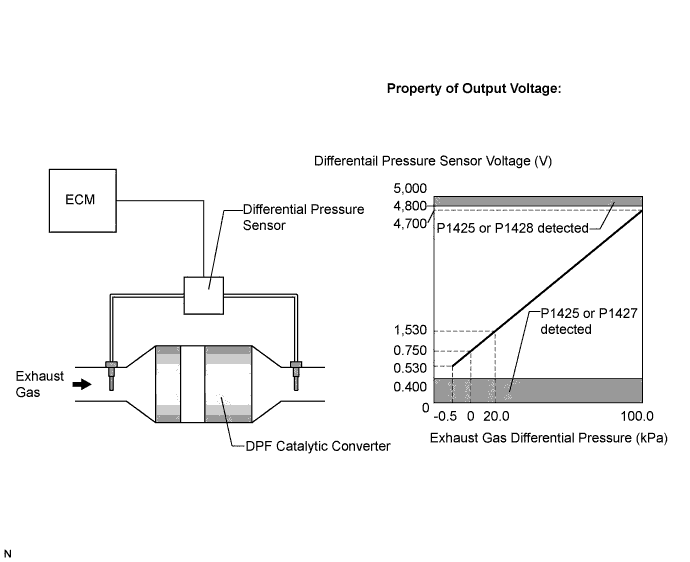
The two sensing chambers of the differential pressure sensor are mounted to monitor the pressure before and after the DPF (*2) catalytic converter. The sensor itself is not located on the engine assembly in order to reduce the influence of vibration. The sensor is a semiconductor-type that is not influenced by exhaust gases.
The ECM compares the exhaust gas pressure before and after DPF catalytic converter by monitoring the pressure using the upstream and downstream sensing chambers of the differential pressure sensor. If the difference between the pressure before and after the catalytic converter exceeds a predetermined level, the ECM judges that the catalytic converter has clogged with particulate matter (PM). When the ECM judges that a partially clogged condition exists, the ECM begins to perform DPF catalyst regeneration.
When the output voltage of the sensor deviates from the normal operating range, the ECM interprets this as a malfunction of the sensor circuit, and sets DTC P1425, P1427, or P1428 and illuminates the MIL.
*2: Diesel Particulate Filter
Tech Tips
If the vacuum hoses of the differential pressure sensor are incorrectly connected (crossed), the ECM interprets this as abnormal pressure difference, DTC P1426 (Differential Pressure Sensor [Installation]) will be set and the MIL will be illuminated.
| DTC No. | DTC Detection Condition | Trouble Area |
|---|---|---|
| P1425 | Differential pressure sensor output voltage is less than 0.4 V, or more than 4.8 V for 1 seconds or more (1 trip detection logic) |
|
| P1427 | Differential pressure sensor output voltage is less than 0.4 V for 1 seconds or more (1 trip detection logic) |
|
| P1428 | Differential pressure sensor output voltage is more than 4.8 V for 1 seconds or more (1 trip detection logic) |
|
Tech Tips
-
DTC P1426 (Differential pressure sensor [installation]) will be present if there is incorrect vacuum hose routing to the differential pressure sensor.
-
After confirming DTC P1425, P1427 and P1428, check the differential pressure by selecting the following menus on the tester: Powertrain / Engine and ECT / Data List / DPNR Differential Pressure.
Result Condition Differential Pressure Output Sensor Condition Ignition Switch in the ON Position Approximately 0 kPa Normal Always -5 kPa or 100 kPa Open or short circuit 3,000 rpm (No engine load) Negative output Incorrect arrangement of hose piping
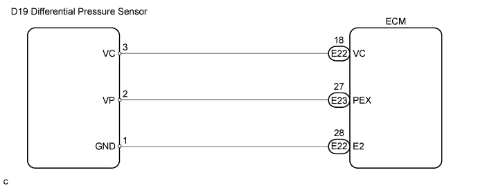
WIRING DIAGRAM
INSPECTION PROCEDURE
PROCEDURE
-
READ VALUE USING INTELLIGENT TESTER (DIFFERENTIAL PRESSURE)
-
Replace the normal DLC3 cable (12 V specification) for the intelligent tester with the 24 V DLC3 cable.
Note
Be sure to use the 24 V DLC3 cable when connecting the intelligent tester to the DLC3. Using the normal DLC3 cable (12 V specification) will cause damage to the tester.
-
Connect the intelligent tester to the DLC3.
-
Turn the ignition switch to the ON position.
-
Turn the tester on.
-
Enter the following menu items: Powertrain / Engine and ECT / Data List / DPR Differential Pressure.
-
Check that differential pressure is within the specification below.
Result Condition Differential Pressure Proceed to Always -5 kPa or less A -1 to 1 kPa B 100 kPa C
B 
CHECK FOR INTERMITTENT PROBLEMS
C 
CHECK BLOCKAGE OF VACUUM HOSE AND CATALYST CONVERTER Click here
A 
-
-
CHECK CONNECTION OF VACUUM HOSE (DIFFERENTIAL PRESSURE SENSOR - CATALYST CONVERTER)
-
Check if the vacuum hose routing between the differential pressure sensor and the catalyst converter is correct.
-
Check that there is no exhaust gas leakage between the differential pressure sensor and the catalyst converter.
NG
RECONNECT TO VACUUM HOSE
OK
-
-
CHECK BLOCKAGE OF VACUUM HOSE AND CATALYST CONVERTER
CAUTION:
Be careful of being burned by exhaust gases during the following inspection.
-
Disconnect the vacuum hose (both upstream and downstream) on the differential pressure sensor.
-
Start the engine.
-
Check if there are exhaust gas pulsations from both vacuum hoses during idling.
NG
REPLACE CLOGGED PARTS
OK
-
-
CHECK HARNESS AND CONNECTOR (DIFFERENTIAL PRESSURE SENSOR - ECM)
-
Disconnect the differential pressure sensor connector.
-
Disconnect the ECM connectors.
-
Measure the resistance according to the value(s) in the table below.
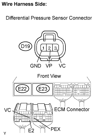
Standard resistance Check for open Tester Connection Condition Specified Condition PEX (E23-27) - VP (D19-2) Always Below 1 Ω VC (E22-18) - VC (D19-3) Always Below 1 Ω E2 (E22-28) - GND (D19-1) Always Below 1 Ω Check for short Tester Connection Condition Specified Condition PEX (E23-27) or VP (D19-2) - Body ground Always 10 kΩ or higher VC (E22-18) or VC (D19-3) - Body ground Always 10 kΩ or higher -
Reconnect the differential pressure sensor connector.
-
Reconnect the ECM connectors.
NG
REPAIR OR REPLACE HARNESS OR CONNECTOR (DIFFERENTIAL PRESSURE SENSOR - ECM)
OK 
REPLACE DIFFERENTIAL PRESSURE SENSOR ASSEMBLY
-