ECD SYSTEM, Diagnostic DTC:P0560

| DTC Code | DTC Name |
|---|---|
| P0560 | System Voltage |
DESCRIPTION
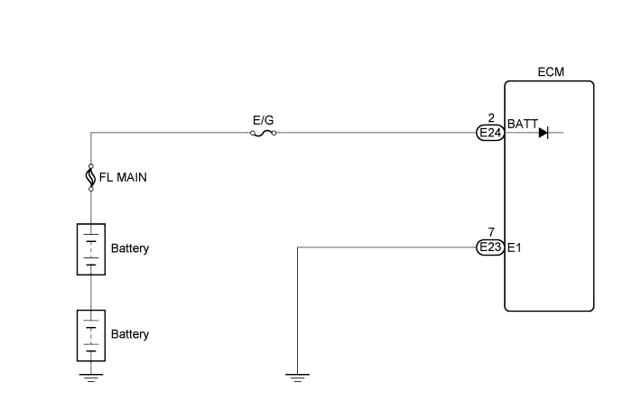
While the ignition switch is off, battery voltage is supplied to terminal BATT of the ECM for storing DTCs and fuel injection feedback learning values.
| DTC No. | DTC Detection Condition | Trouble Area |
|---|---|---|
| P0560 | Condition (a) or (b) continues: (a) Significant decrease in battery voltage (b) Open in back-up power source circuit (1 trip detection logic) |
|
Tech Tips
If DTC P0560 appears, the ECM does not store other DTCs.
WIRING DIAGRAM
INSPECTION PROCEDURE
PROCEDURE
-
INSPECT FUSE (E/G FUSE)
-
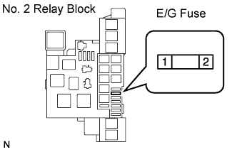
Remove the E/G fuse from the No. 2 relay block.
-
Measure the resistance according to the value(s) in the table below.
Standard resistance Tester Connection Condition Specified Condition 1 - 2 Always Below 1 Ω -
Reinstall the E/G fuse.
NG 
REPLACE FUSE (E/G FUSE)
OK 
-
-
CHECK HARNESS AND CONNECTOR (ECM - BATTERY)
-
Disconnect the negative battery terminal.
-
Disconnect the positive battery terminal.
-
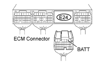
Disconnect the ECM connector.
-
Measure the resistance according to the value(s) in the table below.
Standard resistance Check for open Tester Connection Condition Specified Condition E24-2 (BATT) - Positive battery terminal Always Below 1 Ω Check for short Tester Connection Condition Specified Condition E24-2 (BATT) or Positive battery terminal - Body ground Always 10 kΩ or higher -
Reconnect the ECM connector.
-
Reconnect the positive battery terminal.
-
Reconnect the negative battery terminal.
NG
REPAIR OR REPLACE HARNESS OR CONNECTOR (ECM - BATTERY)
OK
-
-
READ VALUE USING INTELLIGENT TESTER (BATTERY VOLTAGE)
-
Replace the normal DLC3 cable (12 V specification) for the intelligent tester with the 24 V DLC3 cable.
Note
Be sure to use the 24 V DLC3 cable when connecting the intelligent tester to the DLC3. Using the normal DLC3 cable (12 V specification) will cause damage to the tester.
-
Connect the intelligent tester to the DLC3.
-
Turn the ignition switch to the ON position.
-
Turn the tester on.
-
Enter the following menu items: Powertrain / Engine and ECT / Data List / Battery Voltage.
-
Read the values.
Standard voltage 18 to 27 V
NG
REPLACE BATTERY
OK 
REPLACE ECM
-