ECD SYSTEM, Diagnostic DTC:P0335, P0339

| DTC Code | DTC Name |
|---|---|
| P0335 | Crankshaft Position Sensor "A" Circuit |
| P0339 | Crankshaft Position Sensor "A" Circuit Intermittent |
DESCRIPTION
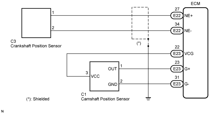
The crankshaft position sensor (NE signal) consists of a magnet, iron core and pickup coil.
The crankshaft angle sensor plate has 32 teeth and is installed on the injection pump drive gear. The NE signal sensor generates 32 signals of every engine revolution. The ECM detects the standard crankshaft angle based on the G signal from the camshaft position sensor, and the actual crankshaft angle and the engine speed by the NE signal.
| DTC No. | DTC Detection Condition | Trouble Area |
|---|---|---|
| P0335 | One of the following conditions is met: (a) No crankshaft position sensor signal to ECM while cranking for 4.7 seconds or more (b) No crankshaft position sensor signal to ECM after cranking (Engine revolution 600 rpm or more) |
|
| P0339 | In conditions (a), (b) and (c), no crankshaft position sensor (NE) signal is input for 0.05 seconds or more. (a) Engine revolution is 1,000 rpm or more (b) NE signal is OFF (c) 3 seconds or more has lapsed after STA signal is switched from ON to OFF |
|
WIRING DIAGRAM
INSPECTION PROCEDURE
Tech Tips
Read freeze frame data using the intelligent tester. The ECM records vehicle and driving condition information as freeze frame data the moment a DTC is stored. When troubleshooting, freeze frame data can be helpful in determining whether the vehicle was running or stopped, whether the engine was warmed up or not, whether the air fuel ratio was lean or rich, as well as other data recorded at the time of a malfunction.
PROCEDURE
-
CHECK CRANKSHAFT POSITION SENSOR
-
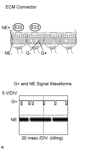
While idling the engine, check the waveform of the ECM connectors using an oscilloscope.
Standard Tester Connection Specified Condition E22-27 (NE+) - E22-34 (NE-) Correct waveform appears as shown E23-23 (G+) - E23-31 (G-) Correct waveform appears as shown
NG 
INSPECT CRANKSHAFT POSITION SENSOR (RESISTANCE) Click here
OK 
CHECK FOR INTERMITTENT PROBLEMS
-
-
INSPECT CRANKSHAFT POSITION SENSOR (RESISTANCE)
-
Disconnect the crankshaft position sensor connector.
-
Measure the resistance according to the value(s) in the table below.
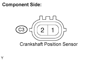
Standard resistance Tester Connection Condition Specified Condition C3-1 - C3-2 Cold 1630 to 2740 Ω C3-1 - C3-2 Hot 2065 to 3225 Ω Note
In the above table, the terms "Cold" and "Hot" refer to the temperature of the coils. "Cold" means approximately -10 to 50°C (14 to 122°F). "Hot" means approximately 50 to 100°C (122 to 212°F).
-
Reconnect the crankshaft position sensor connector.
NG 
REPLACE CRANKSHAFT POSITION SENSOR
OK 
-
-
CHECK HARNESS AND CONNECTOR (CRANKSHAFT POSITION SENSOR - ECM)
-
Disconnect the crankshaft position sensor connector.
-
Disconnect the ECM connector.
-
Measure the resistance according to the value(s) in the table below.
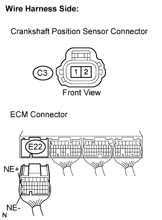
Standard resistance Check for open Tester Connection Condition Specified Condition C3-1 - E22-27 (NE+) Always Below 1 Ω C3-2 - E22-34 (NE-) Always Below 1 Ω Check for short Tester Connection Condition Specified Condition C3-1 or E22-27 (NE+) - Body ground Always 10 kΩ or higher C3-2 or E22-34 (NE-) - Body ground Always 10 kΩ or higher -
Reconnect the crankshaft position sensor connector.
-
Reconnect the ECM connector.
NG
REPAIR OR REPLACE HARNESS OR CONNECTOR (CRANKSHAFT POSITION SENSOR - ECM)
OK
-
-
CHECK CRANKSHAFT POSITION SENSOR (SENSOR INSTALLATION)
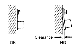
OK The crankshaft position sensor is installed properly.
NG
SECURELY REINSTALL CRANKSHAFT POSITION SENSOR
OK
-
CHECK CRANKSHAFT POSITION SENSOR PLATE
-
Check the teeth of the crankshaft angle sensor plate.
NG
REPLACE CRANKSHAFT POSITION SENSOR PLATE
OK
REPLACE ECM
-