ECD SYSTEM, Diagnostic DTC:P0263, P0266, P0269, P0272

| DTC Code | DTC Name |
|---|---|
| P0263 | Cylinder 1 Contribution / Balance |
| P0266 | Cylinder 2 Contribution / Balance |
| P0269 | Cylinder 3 Contribution / Balance |
| P0272 | Cylinder 4 Contribution / Balance |
DESCRIPTION
Refer to DTC P0200 Click here.
| DTC No. | DTC Detection Condition | Trouble Area |
|---|---|---|
| P0263 P0266 P0269 P0272 |
Conditions (a), (b) and (c) are met more than 200 times with engine speed 500 to 1,000 rpm: (a) Engine coolant temperature: 60°C (140°F) or more (b) Difference of compensation value between cylinders: 15 mm3/sec. or more (c) Injection volume: 0 to 30 mm3/st |
|
Tech Tips
These DTCs indicate a malfunction related to the primary circuit.
-
If DTC P0263 is displayed, check the injector No. 1 circuit.
-
If DTC P0266 is displayed, check the injector No. 2 circuit.
-
If DTC P0269 is displayed, check the injector No. 3 circuit.
-
If DTC P0272 is displayed, check the injector No. 4 circuit.
WIRING DIAGRAM
Refer to DTC P0200 on Click here.
INSPECTION PROCEDURE
Tech Tips
Read freeze frame data using the intelligent tester. The ECM records vehicle and driving condition information as freeze frame data the moment a DTC is stored. When troubleshooting, freeze frame data can be helpful in determining whether the vehicle was running or stopped, whether the engine was warmed up or not, whether the air fuel ratio was lean or rich, as well as other data recorded at the time of a malfunction.
PROCEDURE
-
CHECK EDU (+B VOLTAGE)
-
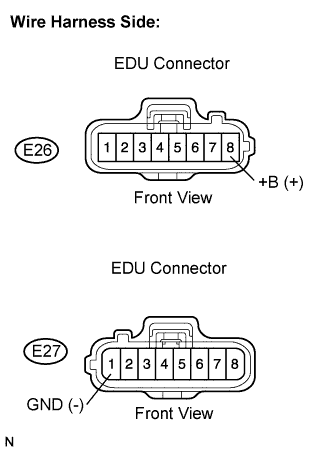
Disconnect the EDU connectors.
-
Measure the voltage according to the value(s) in the table below.
Standard voltage Tester Connection Condition Specified Condition E26-8 (+B) - E27-1 (GND) Ignition switch in the ON position 18 to 27 V -
Reconnect the EDU connectors.
NG 
CHECK EDU POWER SOURCE CIRCUIT
OK 
-
-
CHECK EDU (INJECTOR RESISTANCE)
-
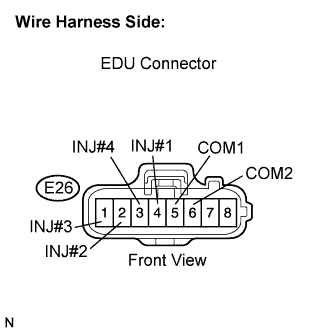
Disconnect the EDU connector.
-
Measure the resistance according to the value(s) in the table below.
Standard resistance Tester Connection Condition Specified Condition E26-4 (INJ#1) - E26-5 (COM1) 20°C (68°F) 0.35 to 0.55 Ω E26-2 (INJ#2) - E26-6 (COM2) 20°C (68°F) 0.35 to 0.55 Ω E26-1 (INJ#3) - E26-6 (COM2) 20°C (68°F) 0.35 to 0.55 Ω E26-3 (INJ#4) - E26-5 (COM1) 20°C (68°F) 0.35 to 0.55 Ω -
Reconnect the EDU connector.
OK 
CHECK HARNESS AND CONNECTOR (EDU - ECM) Click here
NG
-
-
INSPECT INJECTOR ASSEMBLY
-
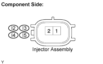
Disconnect the injector connectors.
-
Measure the resistance according to the value(s) in the table below.
Standard resistance Tester Connection Condition Specified Condition 1 - 2 20°C (68°F) 0.35 to 0.55 Ω -
Reconnect the injector connector.
NG
REPLACE INJECTOR ASSEMBLY
OK 
REPAIR OR REPLACE HARNESS OR CONNECTOR (EDU - INJECTOR ASSEMBLY)
-
-
CHECK HARNESS AND CONNECTOR (EDU - ECM)
-
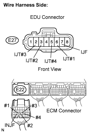
Disconnect the EDU connector.
-
Disconnect the ECM connector.
-
Measure the resistance according to the value(s) in the table below.
Standard resistance Check for open Tester Connection Condition Specified Condition E27-6 (IJT#1) - E22-24 (#1) Always Below 1 Ω E27-3 (IJT#2) - E22-23 (#2) Always Below 1 Ω E27-2 (IJT#3) - E22-22 (#3) Always Below 1 Ω E27-5 (IJT#4) - E22-21 (#4) Always Below 1 Ω E27-7 (IJF) - E22-25 (INJF) Always Below 1 Ω Check for short Tester Connection Condition Specified Condition E27-6 (IJT#1) or E22-24 (#1) - Body ground Always 10 kΩ or higher E27-3 (IJT#2) or E22-23 (#2) - Body ground Always 10 kΩ or higher E27-2 (IJT#3) or E22-22 (#3) - Body ground Always 10 kΩ or higher E27-5 (IJT#4) or E22-21 (#4) - Body ground Always 10 kΩ or higher E27-7 (IJF) or E22-25 (INJF) - Body ground Always 10 kΩ or higher -
Reconnect the EDU connector.
-
Reconnect the ECM connector.
NG
REPAIR OR REPLACE HARNESS OR CONNECTOR (EDU - ECM)
OK
-
-
CHECK ECM (OUTPUT VOLTAGE)
-
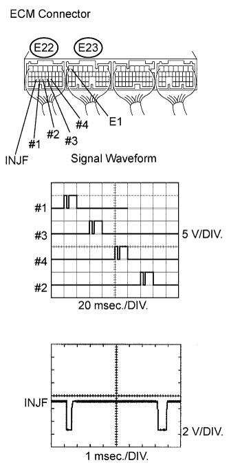
While idling the engine, check the waveform of the ECM connectors using an oscilloscope.
Standard Tester Connection Specified Condition E22-24 (#1) - E23-7 (E1) Correct waveform appears as shown E22-23 (#2) - E23-7 (E1) Correct waveform appears as shown E22-22 (#3) - E23-7 (E1) Correct waveform appears as shown E22-21 (#4) - E23-7 (E1) Correct waveform appears as shown E22-25 (INJF) - E23-7 (E1) Correct waveform appears as shown Result Result Proceed to #1 to #4 is normal INJF is abnormal A #1 to #4 is abnormal INJF is normal B
NG
REPLACE ECM
OK
REPLACE EDU
-