ECD SYSTEM, Diagnostic DTC:P0120, P0122, P0123

| DTC Code | DTC Name |
|---|---|
| P0120 | Throttle / Pedal Position Sensor / Switch "A" Circuit |
| P0122 | Throttle / Pedal Position Sensor / Switch "A" Circuit Low Input |
| P0123 | Throttle / Pedal Position Sensor / Switch "A" Circuit High Input |
DESCRIPTION
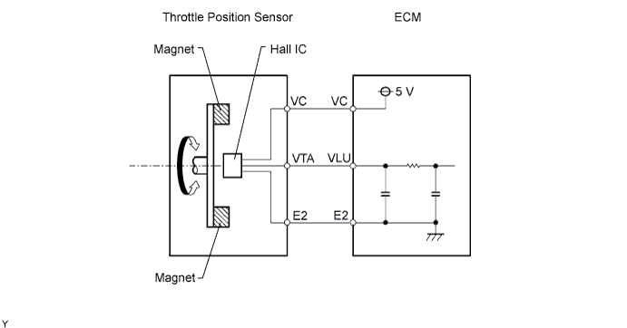
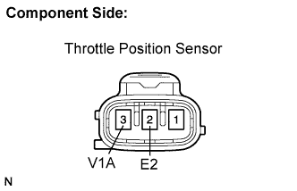
The throttle position sensor is mounted in the throttle body and detects the throttle valve (intake shutter) opening angle.
When the throttle valve is fully closed, a voltage of approximately 0.7 V is applied to terminal VLU of the ECM. The voltage applied to terminal VLU of the ECM increases in proportion to the opening angle of the throttle valve and becomes approximately 3.5 to 4.0 V when the throttle valve is fully opened. The ECM judges the vehicle driving conditions from these signals input from terminal VLU, and uses them as one of the conditions for deciding the air fuel ratio correction, power increase correction and fuel cut control, etc.
| DTC No. | DTC Detection Condition | Trouble Area |
|---|---|---|
| Condition (a) of DTC P0120, P0122 or P0123 continues for 1 second (open or short in throttle position sensor circuit) | ||
| P0120 | Open or short in throttle position sensor circuit for 1 second. |
|
| P0122 | Open in throttle position sensor circuit for 1 second. |
|
| P0123 | Short in throttle position sensor circuit for 1 second. |
|
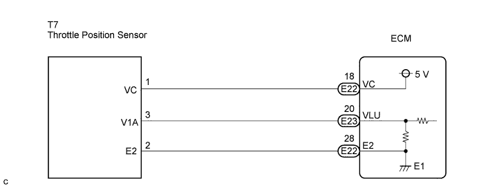
WIRING DIAGRAM
INSPECTION PROCEDURE
Tech Tips
-
If DTCs that are related to different systems are output simultaneously while terminal E2 is used as a ground terminal, terminal E2 may have an open circuit.
-
Read freeze frame data using the intelligent tester. The ECM records vehicle and driving condition information as freeze frame data the moment a DTC is stored. When troubleshooting, freeze frame data can be helpful in determining whether the vehicle was running or stopped, whether the engine was warmed up or not, whether the air fuel ratio was lean or rich, as well as other data recorded at the time of a malfunction.
PROCEDURE
-
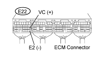
CHECK ECM (VC VOLTAGE)
-
Turn the ignition switch to the ON position.
-
Measure the voltage according to the value(s) in the table below.
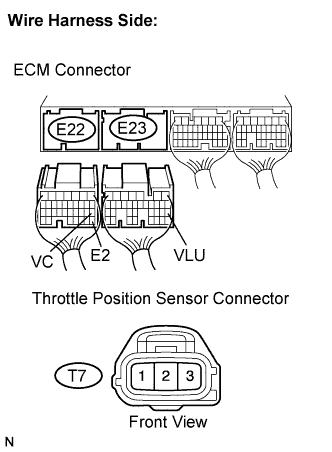
Standard voltage Tester Connection Condition Specified Condition E22-18 (VC) - E22-28 (E2) Always 4.5 to 5.5 V
NG 
REPLACE ECM
OK 
-
-
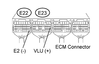
CHECK ECM (VLU VOLTAGE)
-
Turn the ignition switch to the ON position.
-
Measure the voltage according to the value(s) in the table below.
Standard voltage Tester Connection Accelerator Pedal Condition Specified Condition E23-20 (VLU) - E22-28 (E2) Released 2.6 to 3.0 V E23-20 (VLU) - E22-28 (E2) Depressed 1.4 to 1.8 V E23-20 (VLU) - E22-28 (E2) Released → Depressed Voltage changes constantly
NG 
INSPECT THROTTLE POSITION SENSOR Click here
OK 
REPLACE ECM
-
-
INSPECT THROTTLE POSITION SENSOR
-
Disconnect the throttle position sensor connector.
-
Measure the resistance according to the value(s) in the table below.
Standard resistance Tester Connection Throttle Valve Condition Specified Condition T7-3 (V1A) - T7-2 (E2) Fully closed 0.2 to 5.7 kΩ T7-3 (V1A) - T7-2 (E2) Fully open 2.0 to 10.2 kΩ -
Reconnect the throttle position sensor connector.
NG
REPLACE DIESEL THROTTLE BODY
OK
-
-
CHECK HARNESS AND CONNECTOR (ECM - THROTTLE POSITION SENSOR)
-
Disconnect the turbo ECM connectors.
-
Disconnect the throttle position sensor connector.
-
Measure the resistance according to the value(s) in the table below.
Standard resistance Check for open Tester Connection Condition Specified Condition T7-1 (VC) - E22-18 (VC) Always Below 1 Ω T7-3 (V1A) - E23-20 (VLU) Always Below 1 Ω T7-2 (E2) - E22-28 (E2) Always Below 1 Ω Check for short Tester Connection Condition Specified Condition T7-1 (VC) or E22-18 (VC) - Body ground Always 10 kΩ or higher T7-3 (V1A) or E23-20 (VLU) - Body ground Always 10 kΩ or higher -
Reconnect the throttle position sensor connector.
-
Reconnect the ECM connector.
NG
REPAIR OR REPLACE HARNESS OR CONNECTOR (ECM - THROTTLE POSITION SENSOR)
OK
-
-
CHECK DTC OUTPUT
-
Replace the normal DLC3 cable (12 V specification) for the intelligent tester with the 24 V DLC3 cable.
Note
Be sure to use the 24 V DLC3 cable when connecting the intelligent tester to the DLC3. Using the normal DLC3 cable (12 V specification) will cause damage to the tester.
-
Connect the intelligent tester to the DLC3.
-
Turn the ignition switch to the ON position.
-
Turn the tester on.
-
Enter the following menu items: Powertrain / Engine and ECT / DTC.
-
Read the DTCs.
Result Display (DTC output) Proceed to P0120, P0122 and/or P0123 A No output B
NG
CHECK FOR INTERMITTENT PROBLEMS
OK
REPLACE ECM
-