ECD SYSTEM, Diagnostic DTC:P0105, P0107, P0108

| DTC Code | DTC Name |
|---|---|
| P0105 | Manifold Absolute Pressure / Barometric Pressure Circuit |
| P0107 | Manifold Absolute Pressure / Barometric Pressure Circuit Low Input |
| P0108 | Manifold Absolute Pressure / Barometric Pressure Circuit High Input |
DESCRIPTION
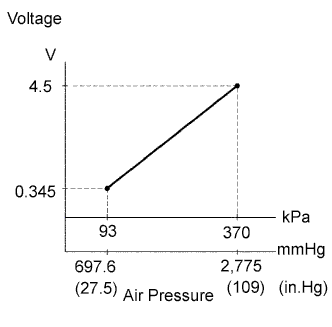
By a built-in sensor unit, the turbo pressure sensor (manifold absolute pressure sensor) detects the intake manifold pressure as a voltage. The ECM then determines the basic injection duration and basic ignition advance angle based on this voltage.
Since the turbo pressure sensor does not use the atmospheric pressure as a criterion, but senses the absolute pressure inside the intake manifold (the pressure in proportion to the preset absolute vacuum 0), it is not influenced by fluctuations in the atmospheric pressure due to high altitude and other factors. This permits it to control the air fuel ratio at the proper level under all conditions.
| DTC No. | DTC Detection Condition | Trouble Area |
|---|---|---|
| P0105 | After engine is started, condition (a) continues for more than 2.0 seconds (a) Open or short in turbo pressure sensor circuit for 0.5 seconds or more |
|
| P0107 | After engine is started, condition (a) continues for more than 2.0 seconds (a) Short in turbo pressure sensor circuit for 0.5 seconds or more |
|
| P0108 | After engine is started, condition (a) continues for more than 2.0 seconds (a) Open in turbo pressure sensor circuit for 0.5 seconds or more |
|
Tech Tips
When DTC P0105, P0107 or P0108 is detected, check the intake manifold pressure by entering the following menus on the intelligent tester: Powertrain / Engine and ECT / Data List / MAP.
| Intake Manifold Pressure (kPa) | Malfunction |
|---|---|
| Approximately 0 | Short in PIM circuit |
| 370 or more |
|
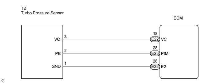
WIRING DIAGRAM
INSPECTION PROCEDURE
Tech Tips
-
If DTCs that are related to different systems are output simultaneously while terminal E2 is used as a ground terminal, terminal E2 may have an open circuit.
-
Read freeze frame data using the intelligent tester. The ECM records vehicle and driving condition information as freeze frame data the moment a DTC is stored. When troubleshooting, freeze frame data can be helpful in determining whether the vehicle was running or stopped, whether the engine was warmed up or not, whether the air fuel ratio was lean or rich, as well as other data recorded at the time of a malfunction.
PROCEDURE
-
READ VALUE USING INTELLIGENT TESTER (MANIFOLD ABSOLUTE PRESSURE)
-
Replace the normal DLC3 cable (12 V specification) for the intelligent tester with the 24 V DLC3 cable.
Note
Be sure to use the 24 V DLC3 cable when connecting the intelligent tester to the DLC3. Using the normal DLC3 cable (12 V specification) will cause damage to the tester.
-
Connect the intelligent tester to the DLC3.
-
Turn the ignition switch to the ON position.
-
Turn the tester on.
-
Enter the following menu items: Powertrain / Engine and ECT / Data List / MAP.
-
Read the value.
Result Pressure Displayed Proceed to 130 kPa A 0 kPa B OK (same as atmospheric pressure near to intake manifold) C
B 
CHECK ECM (PIM VOLTAGE) Click here
C 
CHECK FOR INTERMITTENT PROBLEMS
A 
-
-
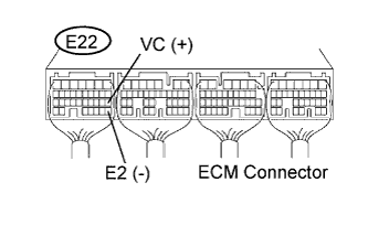
CHECK ECM (VC VOLTAGE)
-
Turn the ignition switch to the ON position.
-
Measure the voltage according to the value(s) in the table below.
Standard voltage Tester Connection Condition Specified Condition E22-18 (VC) - E22-28 (E2) Ignition switch in the ON position 4.5 to 5.5 V
NG
REPLACE ECM
OK
-
-
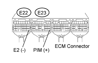
CHECK ECM (PIM VOLTAGE)
-
Turn the ignition switch to the ON position.
-
Measure the voltage according to the value(s) in the table below.
Standard voltage Tester Connection Condition Specified Condition E23-28 (PIM) - E22-28 (E2) Negative pressure of 93 kPa (698 mmHg, 27.5 in.Hg) applied 0.25 to 0.4 V E23-28 (PIM) - E22-28 (E2) Positive pressure of 150 kPa (1,125 mmHg, 44 in.Hg) applied 1.0 to 1.4 V
NG
REPLACE ECM
OK
-
-
CHECK HARNESS AND CONNECTOR (TURBO PRESSURE SENSOR - ECM)
-
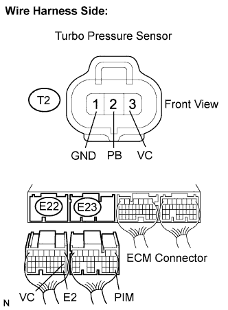
Disconnect the turbo pressure sensor connector.
-
Disconnect the ECM connector.
-
Measure the resistance according to the value(s) in the table below.
Standard resistance Check for open Tester Connection Condition Specified Condition T2-2 (PB) - E23-28 (PIM) Always Below 1 Ω T2-3 (VC) - E22-18 (VC) Always Below 1 Ω T2-1 (GND) - E22-28 (E2) Always Below 1 Ω Check for short Tester Connection Condition Specified Condition T2-2 (PB) or E23-28 (PIM) - Body ground Always 10 kΩ or higher T2-3 (VC) or E22-18 (VC) - Body ground Always 10 kΩ or higher -
Reconnect the turbo pressure sensor connector.
-
Reconnect the ECM connector.
NG
REPAIR OR REPLACE HARNESS OR CONNECTOR (TURBO PRESSURE SENSOR - ECM)
OK 
REPLACE TURBO PRESSURE SENSOR
-