ECD SYSTEM, Diagnostic DTC:P0100, P0102, P0103

| DTC Code | DTC Name |
|---|---|
| P0100 | Mass or Volume Air Flow Circuit |
| P0102 | Mass or Volume Air Flow Circuit Low Input |
| P0103 | Mass or Volume Air Flow Circuit High Input |
DESCRIPTION
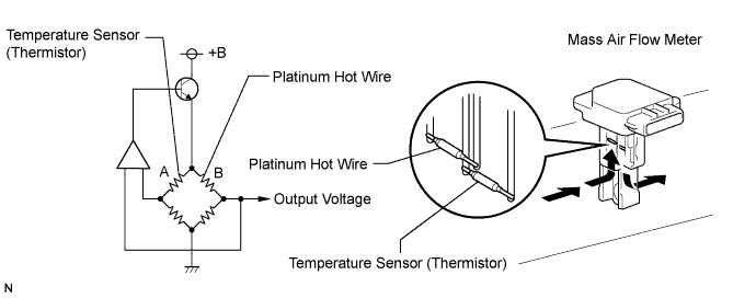
The Mass Air Flow (MAF) meter uses a platinum hot wire. The hot wire MAF meter consists of a platinum hot wire, thermistor and a control circuit installed in a plastic housing. The hot wire MAF meter works on the principle that the hot wire and thermistor located in the intake air bypass of the housing detect any changes in the IAT.
The hot wire is maintained at the set temperature by controlling current flow through the hot wire. This current flow is then measured as the output voltage of the MAF meter.
The circuit is constructed so that the platinum hot wire and thermistor provide a bridge circuit with the power transistor controlled so that the potential of A and B remains equal to maintain the set temperature.
| DTC No. | DTC Detection Condition | Trouble Area |
|---|---|---|
| P0100 | Open or short in MAF meter circuit for more than 3 seconds with engine speed at 4,000 rpm or less |
|
| P0102 | Open in MAF meter circuit for more than 3 seconds with engine speed at 4,000 rpm or less |
|
| P0103 | Short in MAF meter circuit for more than 3 seconds with engine speed at 4,000 rpm or less |
|
Tech Tips
When DTC P0100, P0102 or P0103 is detected, check the mass air flow ratio by selecting the following menus on the intelligent tester: Powertrain / Engine and ECT / Data List / MAF.
| Air Flow Value (gm/sec.) | Malfunction |
|---|---|
| Approx. 0.0 |
|
| 170.1 or more | Open in EVG circuit |
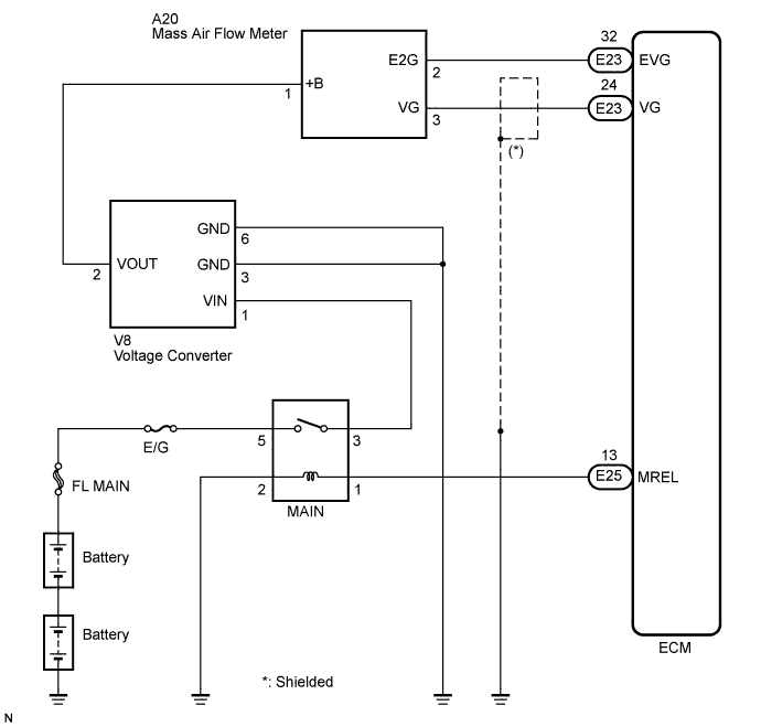
WIRING DIAGRAM
INSPECTION PROCEDURE
Tech Tips
Read freeze frame data using the intelligent tester. The ECM records vehicle and driving condition information as freeze frame data the moment a DTC is stored. When troubleshooting, freeze frame data can be helpful in determining whether the vehicle was running or stopped, whether the engine was warmed up or not, whether the air fuel ratio was lean or rich, as well as other data recorded at the time of a malfunction.
PROCEDURE
-
READ VALUE USING INTELLIGENT TESTER (MAF RATE)
-
Replace the normal DLC3 cable (12 V specification) for the intelligent tester with the 24 V DLC3 cable.
Note
Be sure to use the 24 V DLC3 cable when connecting the intelligent tester to the DLC3. Using the normal DLC3 cable (12 V specification) will cause damage to the tester.
-
Connect the intelligent tester to the DLC3.
-
Start the engine.
-
Turn the tester on.
-
Enter the following menu items: Powertrain / Engine and ECT / Data List / MAF.
-
Read the value.
Result Air Flow Rate (gm/s) Proceed to 0.0 A 170.1 or more B Between 1.6 and 170.0* C Tech Tips
*: The value should change when the throttle valve is opened or closed.
B 
CHECK HARNESS AND CONNECTOR (MASS AIR FLOW METER - ECM) Click here
C 
CHECK FOR INTERMITTENT PROBLEMS
A 
-
-
CHECK MASS AIR FLOW METER (POWER SOURCE)
-
Disconnect the MAF meter connector.
-
Turn the ignition switch to the ON position.
-
Measure the voltage according to the value(s) in the table below.
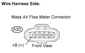
Standard voltage Tester Connection Condition Specified Condition A20-1 (+B) - Body ground Always 13 to 17 V -
Reconnect the MAF meter connector.
NG
CHECK HARNESS AND CONNECTOR (VOLTAGE CONVERTER - MASS AIR FLOW METER) Click here
OK
-
-
INSPECT ECM (VG VOLTAGE)
-
Start the engine.
-
Measure the voltage according to the value(s) in the table below.
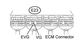
Standard voltage Tester Connection Condition Specified Condition E23-24 (VG) - E23-32 (EVG) Engine is idling 1.8 to 2.6 V E23-24 (VG) - E23-32 (EVG) Engine speed at 3,000 rpm 3.0 to 4.0 V Tech Tips
The A/C switch should be turned off.
NG
CHECK HARNESS AND CONNECTOR (MASS AIR FLOW METER - ECM) Click here
OK 
REPLACE ECM
-
-
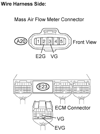
CHECK HARNESS AND CONNECTOR (MASS AIR FLOW METER - ECM)
-
Disconnect the MAF meter connector.
-
Disconnect the ECM connector.
-
Measure the resistance according to the value(s) in the table below.
Standard resistance Check for open Tester Connection Condition Specified Condition A20-3 (VG) - E23-24 (VG) Always Below 1 Ω A20-2 (E2G) - E23-32 (EVG) Always Below 1 Ω Check for short Tester Connection Condition Specified Condition A20-3 (VG) or E23-24 (VG) - Body ground Always 10 kΩ or higher -
Reconnect the MAF meter connector.
-
Reconnect the ECM connector.
NG
REPAIR OR REPLACE HARNESS OR CONNECTOR (MASS AIR FLOW METER - ECM)
OK
REPLACE MASS AIR FLOW METER
-
-
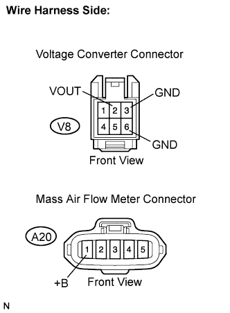
CHECK HARNESS AND CONNECTOR (VOLTAGE CONVERTER - MASS AIR FLOW METER)
-
Disconnect the voltage converter connector.
-
Disconnect the MAF meter connector.
-
Measure the resistance according to the value(s) in the table below.
Standard resistance Check for open Tester Connection Condition Specified Condition V8-2 (VOUT) - A20-1 (+B) Always Below 1 Ω V8-3 (GND) - Body ground Always Below 1 Ω V8-6 (GND) - Body ground Always Below 1 Ω Check for short Tester Connection Condition Specified Condition V8-2 (VOUT) or A20-1 (+B) - Body ground Always 10 kΩ or higher -
Reconnect the MAF meter connector.
-
Reconnect the voltage converter connector.
NG
REPAIR OR REPLACE HARNESS OR CONNECTOR (VOLTAGE CONVERTER - MASS AIR FLOW METER)
OK
-
-
INSPECT VOLTAGE CONVERTER ASSEMBLY (VIM VOLTAGE)
-

Turn the ignition switch to the ON position.
-
Disconnect the voltage converter connector.
-
Measure the voltage according to the value(s) in the table below.
Standard voltage Tester Connection Condition Specified Condition V8-1 (VIN) - V8-3 (GND) Ignition switch in the ON position 18 to 27 V -
Reconnect the voltage converter connector.
NG
CHECK VOLTAGE CONVERTER CIRCUIT
OK
REPLACE VOLTAGE CONVERTER
-