ECD SYSTEM, Diagnostic DTC:P0093

| DTC Code | DTC Name |
|---|---|
| P0093 | Fuel System Leak Detected - Large Leak |
DESCRIPTION
Refer to DTC P0087 Click here.
Refer to DTC P0088 Click here.
| DTC No. | DTC Detection Condition | Trouble Area |
|---|---|---|
| P0093 | DTC is output when following conditions (a), (b) and (c) are all met and if difference of common rail pressure that fuel pressure sensor detects before and after fuel injection varies greatly from difference of value that ECM calculates before and after fuel injection, ECM determines that there may be fuel leaks. (a) Engine RPM is 1,500 rpm or higher. (b) Fuel pressure sensor is normal (P0190, P0191, P0192, and P0193 are not detected). (c) Suction control valve is normal (P0088, P0627 and P1229 are not detected). |
|
INSPECTION PROCEDURE
Note
-
After replacing the ECM, the new ECM needs registration Click here and initialization Click here.
-
After replacing the supply pump, the ECM needs initialization Click here.
-
After replacing the injector, the ECM needs registration Click here.
Tech Tips
Read freeze frame data using the intelligent tester. The ECM records vehicle and driving condition information as freeze frame data the moment a DTC is stored. When troubleshooting, freeze frame data can be helpful in determining whether the vehicle was running or stopped, whether the engine was warmed up or not, whether the air-fuel ratio was lean or rich, as well as other data recorded at the time of a malfunction.
PROCEDURE
-
CHECK OTHER DTC OUTPUT
-
Replace the normal DLC3 cable (12 V specification) for the intelligent tester with the 24 V DLC3 cable.
Note
Be sure to use the 24 V DLC3 cable when connecting the intelligent tester to the DLC3. Using the normal DLC3 cable (12 V specification) will cause damage to the tester.
-
Connect the intelligent tester to the DLC3.
-
Turn the ignition switch to the ON position.
-
Turn the tester on.
-
Enter the following menu items: Powertrain / Engine and ECT / DTC.
-
Rear the DTCs.
Result Display (DTC output) Proceed to P0087, P0190, P0192, P0193, P0200, P0088, P0627 or P1229 is output A No output B
B 
GO TO DTC CHART
A 
-
-
PERFORM ACTIVE TEST USING INTELLIGENT TESTER (TEST THE FUEL LEAK)
Tech Tips
By performing this Active Test, the engine speed is maintained at 2,000 rpm and the common rail internal fuel pressure is raised to the maximum operating pressure. As a result, a fuel leak check can be conducted while retaining the high common rail pressure.
-
Connect the intelligent tester to the DLC3.
-
Start the engine.
-
Turn the tester on.
-
Enter the following menu items: Powertrain / Engine and ECT / Active Test / Test the Fuel Leak.
-
Visually check the supply pump, injector and fuel line located between the supply pump and common rail for fuel leaks and fuel pressure leaks. Also, perform the same check on the fuel line between the common rail and the injector.
Tech Tips
There may be fuel leaks inside the components, such as the supply pump.
OK No leakage.
NG
REPAIR OR REPLACE FUEL LEAKAGE POINT
OK
-
-
INSPECT INJECTION OR SUPPLY PUMP ASSEMBLY (SUCTION CONTROL VALVE)
-
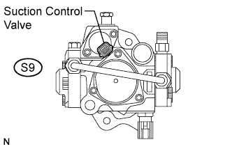
Disconnect the suction control valve connector.
-
Measure the resistance according to the value(s) in the table below.
Standard resistance Tester Connection Condition Specified Condition S9-1 - S9-2 20°C (68°F) 7.6 to 8.2 Ω -
Reconnect the suction control valve connector.
NG
REPLACE INJECTION OR SUPPLY PUMP ASSEMBLY
OK
-
-
INSPECT INJECTION OR SUPPLY PUMP ASSEMBLY (SUCTION CONTROL VALVE)
-
Disconnect the suction control valve connector and then start the engine.
OK Engine does not start.
NG
REPLACE INJECTION OR SUPPLY PUMP ASSEMBLY
OK
-
-
READ VALUE USING INTELLIGENT TESTER (PCV OPEN CURRENT FB VAL)
-
Replace the normal DLC3 cable (12 V specification) for the intelligent tester with the 24 V DLC3 cable.
Note
Be sure to use the 24 V DLC3 cable when connecting the intelligent tester to the DLC3. Using the normal DLC3 cable (12 V specification) will cause damage to the tester.
-
Connect the intelligent tester to the DLC3.
-
Start the engine.
-
Turn the tester on.
-
Enter the following menu items: Powertrain / Engine and ECT / Data List / PCV Open Current FB Val.
-
Read the value.
Standard Engine Speed Result Idling -400 to 400 mA
NG
REPLACE INJECTION OR SUPPLY PUMP ASSEMBLY
OK
-
-
READ VALUE USING INTELLIGENT TESTER (FUEL PRESSURE)
-
Replace the normal DLC3 cable (12 V specification) for the intelligent tester with the 24 V DLC3 cable.
Note
Be sure to use the 24 V DLC3 cable when connecting the intelligent tester to the DLC3. Using the normal DLC3 cable (12 V specification) will cause damage to the tester.
-
Connect the intelligent tester to the DLC3.
-
Start the engine.
-
Turn the tester on.
-
Enter the following menu items: Powertrain / Engine and ECT / Data List / Fuel Press.
-
Check that the internal fuel pressure of the common rail is within the specification below.
Standard Engine Speed Fuel Pressure Idling Approximately 25 to 35 MPa 3,000 rpm (No engine load) Approximately 80 to 90 MPa
OK 
CHECK HARNESS AND CONNECTOR (SUCTION CONTROL VALVE - ECM) Click here
NG
-
-
CHECK HARNESS AND CONNECTOR (ECM - FUEL PRESSURE SENSOR)
-
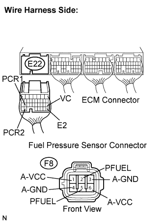
Disconnect the ECM connector.
-
Disconnect the fuel pressure sensor connector.
-
Measure the resistance according to the value(s) in the table below.
Standard resistance Check for open Tester Connection Condition Specified Condition E22-26 (PCR1) - F8-5 (PFUEL) Always Below 1 Ω E22-33 (PCR2) - F8-2 (PFUEL) Always Below 1 Ω E22-18 (VC) - F8-6 (A-VCC) Always Below 1 Ω E22-18 (VC) - F8-1 (A-VCC) Always Below 1 Ω E22-28 (E2) - F8-4 (A-GND) Always Below 1 Ω E22-28 (E2) - F8-3 (A-GND) Always Below 1 Ω Check for short Tester Connection Condition Specified Condition E22-26 (PCR1) or F8-5 (PFUEL) - Body ground Always 10 kΩ or higher E22-33 (PCR2) or F8-2 (PFUEL) - Body ground Always 10 kΩ or higher E22-18 (VC) or F8-6 (A-VCC) - Body ground Always 10 kΩ or higher E22-18 (VC) or F8-1 (A-VCC) - Body ground Always 10 kΩ or higher -
Reconnect the fuel pressure sensor connector.
-
Reconnect the ECM connector.
NG
REPAIR OR REPLACE HARNESS OR CONNECTOR (ECM - FUEL PRESSURE SENSOR)
OK
-
-
READ VALUE USING INTELLIGENT TESTER (FUEL PRESSURE)
-
Replace the normal DLC3 cable (12 V specification) for the intelligent tester with the 24 V DLC3 cable.
Note
Be sure to use the 24 V DLC3 cable when connecting the intelligent tester to the DLC3. Using the normal DLC3 cable (12 V specification) will cause damage to the tester.
-
Connect the intelligent tester to the DLC3.
-
Start the engine.
-
Turn the tester on.
-
Enter the following menu items: Powertrain / Engine and ECT / Data List / Fuel press.
-
Wiggle the fuel pressure sensor connector and check that the fuel pressure reading does not change.
OK The fuel pressure reading does not change.
NG
REPLACE COMMON RAIL ASSEMBLY
OK
-
-
PERFORM INITIALIZATION (INJECTION OR SUPPLY PUMP)
-
Perform initialization Click here.
NEXT
-
-
CHECK WHETHER DTC OUTPUT RECURS (P0093)
-
Clear the DTC Click here.
-
Warm up the engine.
-
Drive the vehicle by 1500 rpm or more for 5 minutes.
-
Enter the following menu items: Powertrain / Engine and ECT / DTC.
-
Read the DTC.
Result Display (DTC output) Proceed to No DTC output A P0093 B
B
REPLACE INJECTION OR SUPPLY PUMP ASSEMBLY
A 
SYSTEM OK
-
-
CHECK HARNESS AND CONNECTOR (SUCTION CONTROL VALVE - ECM)
-
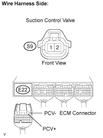
Disconnect the suction control valve connector.
-
Disconnect the ECM connector.
-
Measure the resistance according to the value(s) in the table below.
Standard resistance Check for open Tester Connection Condition Specified Condition E22-2 (PCV+) - S9-1 Always Below 1 Ω E22-1 (PCV-) - S9-2 Always Below 1 Ω Check for short Tester Connection Condition Specified Condition E22-2 (PCV+) or S9-1 - Body ground Always 10 kΩ or higher E22-1 (PCV-) or S9-2 - Body ground Always 10 kΩ or higher -
Reconnect the suction control valve connector.
-
Reconnect the ECM connector.
NG
REPAIR OR REPLACE HARNESS OR CONNECTOR (SUCTION CONTROL VALVE - ECM)
OK
-
-
INSPECT ECM (PCR VOLTAGE)
-
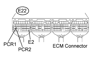
Start the engine.
-
Measure the voltage according to the value(s) in the table below.
Standard voltage Tester Connection Condition Specified Condition E22-26 (PCR1) - E22-28 (E2) Idling 1.7 to 2.2 V E22-33 (PCR2) - E22-28 (E2) Idling 1.2 to 1.6 V
NG
REPLACE COMMON RAIL ASSEMBLY
OK
REPLACE INJECTOR ASSEMBLY
-