ECD SYSTEM DPF Switch and Buzzer Circuit
DESCRIPTION
The DPF (Diesel Particulate Filter) is controlled by the ECM to activate the forcible regeneration function automatically. However, depending on driving conditions, the forcible regeneration function may not be activated. In such a case, the indicator light on the combination meter and the DPF switch light blink to inform the driver. When the DPF switch is pressed with the vehicle stopped, RGSW signals will be input into the ECM and the forcible regeneration function will activate.
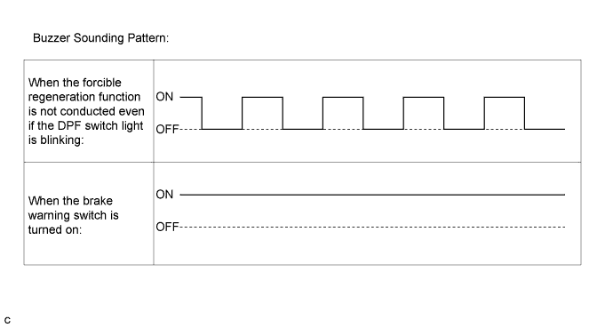
If the vehicle continues to be driven without performing forcible regeneration while the indicator light is ON, a buzzer intermittently sounds to inform the driver.
Tech Tips
If the buzzer intermittently sounds, the brake vacuum warning switch may have been turned on.
In this case, inspect the brake vacuum warning switch circuit first.
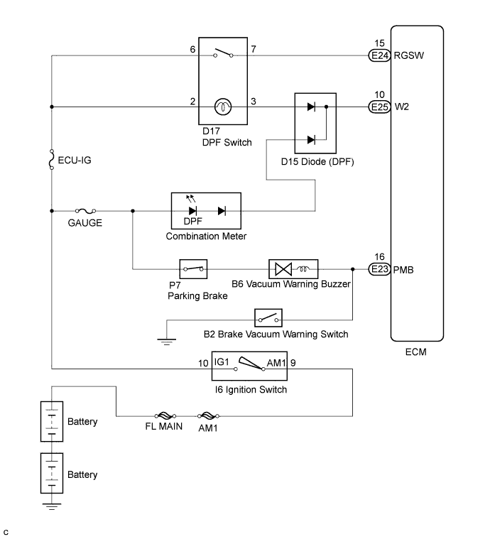
WIRING DIAGRAM
INSPECTION PROCEDURE
PROCEDURE
-
CHECK BUZZER OPERATION
-
Check the buzzer sounds.
Result Sounds Proceed to The buzzer sounds intermittently A The buzzer sounds continuously B
B 
CHECK BRAKE VACUUM WARNING BUZZER CIRCUIT
A 
-
-
CHECK DPF SWITCH (POWER SOURCE)
-
Disconnect the DPF switch connector.
-
Turn the ignition switch to the ON position.
-
Measure the voltage according to the value(s) in the table below.
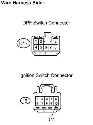
Standard voltage Tester Connection Condition Specified Condition D7-6 - Body ground Ignition switch in the ON position 18 to 27 V D7-2 - Body ground Ignition switch in the ON position 18 to 27 V -
Turn the ignition switch off.
-
Reconnect the DPF switch.
NG 
INSPECT DPF SWITCH ASSEMBLY (ILLUMINATED) Click here
OK
-
-
INSPECT DPF SWITCH ASSEMBLY (RESISTANCE)
-
Disconnect the DPF switch connector.
-
Measure the resistance according to the value(s) in the table below.
Standard resistance Tester Connection Condition Specified Condition D17-6 - D17-7 DPF switch on Below 1 Ω D17-6 - D17-7 DPF switch off 10 kΩ or higher -
Reconnect the DPF switch connector.
NG
INSPECT IGNITION SWITCH ASSEMBLY Click here
OK
-
-
INSPECT DPF SWITCH ASSEMBLY (ILLUMINATED)
-
Remove the DPF switch.
-
Check that the illumination comes on.
Result Connector Connection Condition Illumination Apply the battery voltage terminal D17-2 (+) and D17-3 (-) Always Comes on -
Reinstall the DPF switch.
NG
REPAIR OR REPLACE HARNESS OR CONNECTOR (IGNITION SWITCH - BATTERY)
OK
-
-
CHECK HARNESS AND CONNECTOR (DPF SWITCH - ECM)
-
Disconnect the DPF switch connector.
-
Disconnect the ECM connector.
-
Measure the resistance according to the value(s) in the table below.
Standard resistance Check for open Tester Connection Condition Specified Condition D17-7 - E24-15 (RGSW) Always Below 1 Ω D17-3 - E25-10 (W2) Always Below 1 Ω Check for short Tester Connection Condition Specified Condition D17-7 or E24-15 (RGSW) - Body ground Always 10 kΩ or higher D17-3 or E25-10 (W2) - Body ground Always 10 kΩ or higher -
Reconnect the DPF switch.
-
Reconnect the ECM connector.
NG
REPLACE DPF SWITCH ASSEMBLY
OK 
REPLACE DPF SWITCH ASSEMBLY
-
-
INSPECT FUSE (ECU-IG FUSE)
-
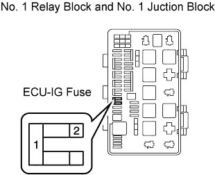
Remove the ECU-IG fuse from the No. 1 relay block and No. 1 junction block.
-
Measure the resistance according to the value(s) in the table below.
Standard resistance Tester Connection Condition Specified Condition 1 - 2 Always Below 1 Ω -
Reinstall the ECU-IG fuse.
NG
REPAIR OR REPLACE HARNESS OR CONNECTOR (DPF SWITCH - ECM)
OK
-
-
CHECK HARNESS AND CONNECTOR (DPF SWITCH - IGNITION SWITCH)
-
Disconnect the DPF switch connector.
-
Disconnect the ignition switch connector.
-
Measure the resistance according to the value(s) in the table below.
Standard resistance Check for open Tester Connection Condition Specified Condition D17-6 - I6-10 (IG1) Always Below 1 Ω D17-2 - I6-10 (IG1) Always Below 1 Ω Check for short Tester Connection Condition Specified Condition D17-6 or I6-10 (IG1) - Body ground Always 10 kΩ or higher D17-2 or I6-10 (IG1) - Body ground Always 10 kΩ or higher -
Reconnect the DPF switch connector.
-
Reconnect the ignition switch connector.
NG
PROCEED TO NEXT CIRCUIT INSPECTION SHOWN IN PROBLEM SYMPTOMS TABLE
OK
-
-
INSPECT IGNITION SWITCH ASSEMBLY
-
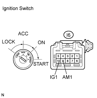
Disconnect the ignition switch connector.
-
Measure the resistance according to the value(s) in the table below.
Standard resistance Tester Connection Ignition Switch Position Specified Condition All terminals LOCK 10 kΩ or higher I6-9 (AM1) - I6-10 (IG1) ON Below 1 Ω -
Reconnect the ignition switch connector.
NG
REPLACE FUSE (ECU-IG FUSE)
OK
CHECK HARNESS AND CONNECTOR (DPF SWITCH - IGNITION SWITCH)
-