ECD SYSTEM VC Output Circuit
DESCRIPTION
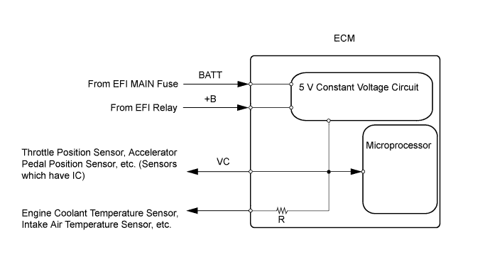
The ECM constantly uses 5 V from the battery voltages supplied to the +B (BATT) terminal to operate the microprocessor. The ECM also provides this power to the sensors through the VC output circuit.
When the VC circuit is short-circuited, the microprocessor in the ECM and sensors that obtain power through the VC circuit are deactivated because power is not supplied from the VC circuit. Under this condition, the system does not start up and the MIL is not illuminated even if the system malfunctions.
Tech Tips
Under normal conditions, the MIL is illuminated for several seconds when the ignition switch is first turned to the ON position. The MIL goes off when the engine is started.
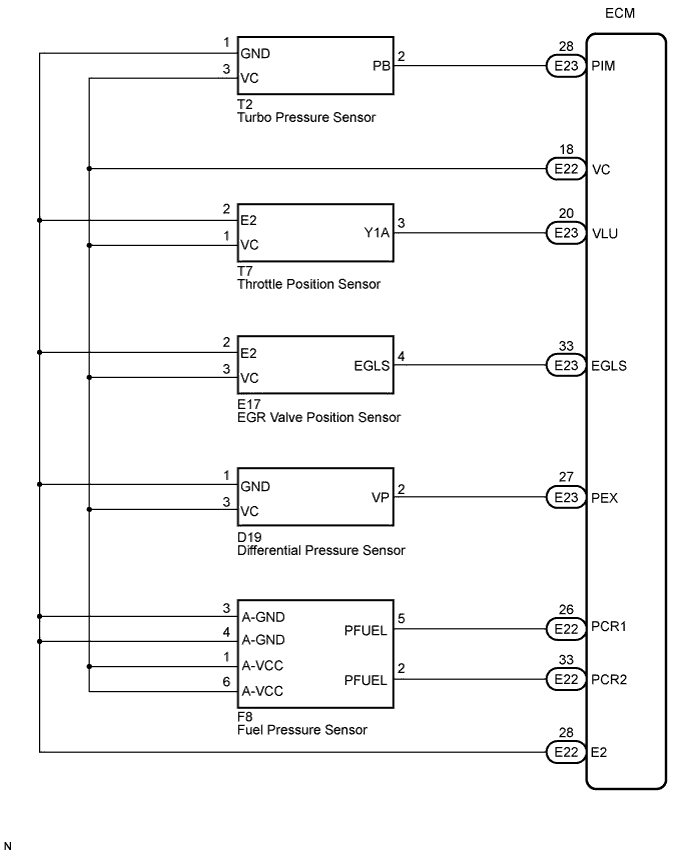
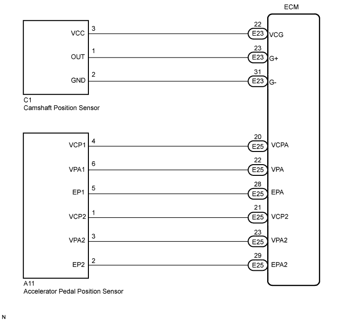
WIRING DIAGRAM
INSPECTION PROCEDURE
PROCEDURE
-
CHECK MIL
-
Check that the Malfunction Indicator Lamp (MIL) lights up when turning the ignition switch to the ON position.
OK MIL lights up.
OK 
GO TO MIL CIRCUIT Click here
NG 
-
-
CHECK CONNECTION BETWEEN INTELLIGENT TESTER AND ECM
-
Replace the normal DLC3 cable (12 V specification) for the intelligent tester with the 24 V DLC3 cable.
Note
Be sure to use the 24 V DLC3 cable when connecting the intelligent tester to the DLC3. Using the normal DLC3 cable (12 V specification) will cause damage to the tester.
-
Connect the intelligent tester to the DLC3.
-
Turn the ignition switch to the ON position and tester on.
-
Check the communication between the tester and ECM.
Result Result Proceed to Communication is possible A Communication is not possible B
A
GO TO MIL CIRCUIT Click here
B
-
-
CHECK DIESEL THROTTLE BODY (CHECK MIL ILLUMINATED)
-
Disconnect the throttle position sensor connector.
-
Turn the ignition switch to the ON position.
-
Check the MIL.
Result Result Proceed to MIL is illuminated A MIL is not illuminated B -
Reconnect the throttle position sensor connector.
A
REPLACE DIESEL THROTTLE BODY ASSEMBLY
B
-
-
CHECK ACCELERATOR PEDAL (CHECK MIL ILLUMINATED)
-
Disconnect the accelerator pedal position sensor connector.
-
Turn the ignition switch to the ON position.
-
Check the MIL.
Result Result Proceed to MIL is illuminated A MIL is not illuminated B -
Reconnect the accelerator pedal position sensor connector.
A
REPLACE ACCELERATOR PEDAL ASSEMBLY
B
-
-
CHECK CAMSHAFT POSITION SENSOR (CHECK MIL ILLUMINATED)
-
Disconnect the connector from the camshaft position sensor.
-
Turn the ignition switch to the ON position.
-
Check the MIL.
Result Result Proceed to MIL is illuminated A MIL is not illuminated B -
Reconnect the connector to the camshaft position sensor.
A
REPLACE CAMSHAFT POSITION SENSOR
B
-
-
CHECK TURBO PRESSURE SENSOR (CHECK MIL ILLUMINATED)
-
Disconnect the connector from the turbo pressure sensor.
-
Turn the ignition switch to the ON position.
-
Check the MIL.
Result Result Proceed to MIL is illuminated A MIL is not illuminated B -
Reconnect the connector to the turbo pressure sensor.
A
REPLACE TURBO PRESSURE SENSOR
B
-
-
CHECK EGR VALVE POSITION SENSOR (CHECK MIL ILLUMINATED)
-
Disconnect the connector from the EGR valve position sensor.
-
Turn the ignition switch to the ON position.
-
Check the MIL.
Result Result Proceed to MIL is illuminated A MIL is not illuminated B -
Reconnect the connector to the EGR valve position sensor.
A
REPLACE EGR VALVE ASSEMBLY (EGR VALVE POSITION SENSOR)
B
-
-
CHECK DIFFERENTIAL PRESSURE SENSOR (CHECK MIL ILLUMINATED)
-
Disconnect the connector from the differential pressure sensor.
-
Turn the ignition switch to the ON position.
-
Check the MIL.
Result Result Proceed to MIL is illuminated A MIL is not illuminated B -
Reconnect the connector from the differential pressure sensor.
A
REPLACE DIFFERENTIAL PRESSURE SENSOR
B
-
-
CHECK HARNESS AND CONNECTOR
-
Disconnect the throttle position sensor connector.
-
Disconnect the accelerator pedal position sensor connector.
-
Disconnect the connector from the camshaft position sensor.
-
Disconnect the connector from the turbo pressure sensor.
-
Disconnect the connector from the EGR valve position sensor.
-
Disconnect the connector from the differential pressure sensor.
-
Disconnect the ECM connector.
-
Measure the resistance according to the value(s) in the table below.
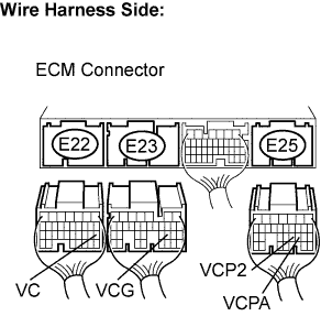
Standard resistance Check for short Tester Connections Condition Specified Conditions E25-21 (VCP2) - Body ground Always 10 kΩ or higher E25-20 (VCPA) - Body ground Always 10 kΩ or higher E23-22 (VCG) - Body ground Always 10 kΩ or higher E22-18 (VC) - Body ground Always 10 kΩ or higher -
Reconnect the ECM connectors.
-
Reconnect the connector to the differential pressure sensor.
-
Reconnect the connector to the EGR valve position sensor.
-
Reconnect the connector to the turbo pressure sensor.
-
Reconnect the connector to the camshaft position sensor.
-
Reconnect the accelerator pedal position sensor.
-
Reconnect the throttle position sensor connector.
NG
REPAIR OR REPLACE HARNESS OR CONNECTOR
OK 
REPLACE ECM Click here
-