CAN COMMUNICATION SYSTEM, Diagnostic DTC:U0100

| DTC Code | DTC Name |
|---|---|
| U0100 | Lost Communication with ECM / PCM "A" |
DESCRIPTION
| DTC Code | DTC Detection Condition | Trouble Area |
|---|---|---|
| U0100 | There is no communication from the ECM. |
|
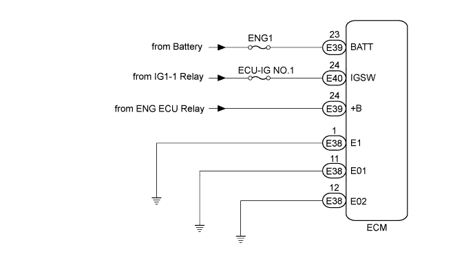
WIRING DIAGRAM
INSPECTION PROCEDURE
Note
Inspect the fuses for circuits related to this system before performing the following inspection procedure.
PROCEDURE
-
CHECK HARNESS AND CONNECTOR (ECM - BATTERY AND BODY GROUND)
-
Disconnect the ECM connectors.
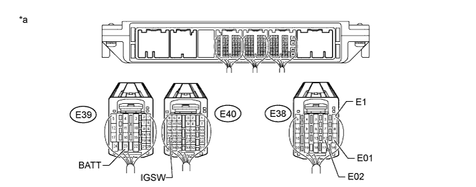
Text in Illustration *a Rear view of wire harness connector
(to ECM)
- - -
Measure the resistance according to the value(s) in the table below.
Standard Resistance Tester Connection Condition Specified Condition E38-1 (E1) - Body ground Always Below 1 Ω E38-11 (E01) - Body ground Always Below 1 Ω E38-12 (E02) - Body ground Always Below 1 Ω -
Measure the voltage according to the value(s) in the table below.
Standard Voltage Tester Connection Condition Specified Condition E39-23 (BATT) - Body ground Always 20 to 28 V E40-24 (IGSW) - Body ground Ignition switch ON 20 to 28 V
NG 
REPAIR OR REPLACE HARNESS OR CONNECTOR
OK 
-
-
CHECK ECM POWER SOURCE CIRCUIT
-
Check the ECM power source circuit Click here.
NG
REPAIR OR REPLACE HARNESS OR CONNECTOR (POWER SOURCE CIRCUIT)
OK 
REPLACE ECM Click here
-