CAN COMMUNICATION SYSTEM DIAGNOSIS SYSTEM

-
BUS CHECK (COMMUNICATION MALFUNCTION ECU)
Only CAN communication system DTCs for each ECU can be output to the intelligent tester.
-
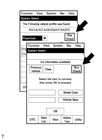
Select "Bus Check" from the "System Select" screen on the intelligent tester.
-
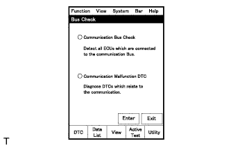
Select "Communication Malfunction DTC" from the "Bus Check" screen, and then select "Enter".
-
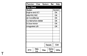
Select the system of the DTC to be checked and select "Details".
-
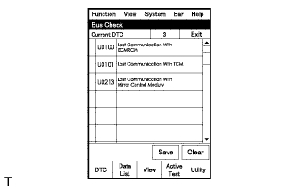
CAN communication system DTCs are output.
-
-
BUS CHECK (COMMUNICATION BUS CHECK)
Tech Tips
The ECUs and sensors that are properly connected to the CAN communication system can be displayed using the intelligent tester.
-
Select "Communication Bus Check" from the "Bus Check" screen.
-
The screen displays the ECUs and sensors that are properly connected to the CAN communication system.
Tech Tips
-
If any properly connected ECUs or sensors are not displayed, there is a communication stop in the system Click here.
-
The default item displayed in the combo box is "ALL". When checking the ECUs (sensors) connected to each bus, pull down the combo box and select the bus to be checked from the dropdown list. The drop-down list displays "ALL", "V Bus" and the names of the remaining buses.
Combo Box Display Content ALL All ECUs (sensors) connected to the CAN bus V Bus ECUs (sensors) connected to the V Bus Bus Name ECUs (sensors) connected to the selected bus -
The connection status (shown below) is indicated by the background color displayed behind the system name.
ECU (Sensor) on V Bus Background Color Connection Status White Detected normally Yellow Could not be detected in the past, but is currently detected Red Detected in the past, but cannot be detected now Not displayed Has never been detected ECU (Sensor) with No Data Monitor History Background Color Connection Status White Detected normally Yellow Could not be detected in the past, but is currently detected Red Detected in the past, but cannot be detected now Not displayed Has never been detected ECU (Sensor) with Data Monitor History Background Color Connection Status White Detected normally Yellow Could not be detected in the past, but is currently detected Red Detected in the past, but cannot be detected now Red Has never been detected but has connection history Not displayed Has never been detected
-
-
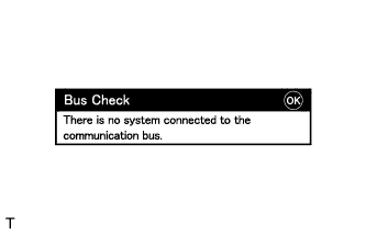
"There is no system connected to the communication bus." is displayed if there are no ECUs or sensors connected to the CAN bus.
-
-
CHECK INSTALLED SYSTEMS (ECUS AND SENSORS) THAT USE CAN COMMUNICATION
-
Systems (ECUs and sensors) that use CAN communication vary depending on the optional settings of the vehicle. Check which systems (ECUs and sensors) are installed on the vehicle.
ECU/Sensor Name Tester Display Installed on ECM ECM (Engine) All vehicles Electric vehicle control ECU assembly Electric Vehicle Control All vehicles Brake actuator assembly (skid control ECU) Skid Control (ABS/VSC/TRAC) All vehicles Airbag ECU assembly Airbag All vehicles Combination meter assembly Combination Meter All vehicles Turbocharger sub-assembly - All vehicles EGR valve assembly - All vehicles
-
-
DTC TABLE BY ECU
Tech Tips
-
In the CAN communication system, CAN communication system DTCs stored by the ECU can be output by using the intelligent tester.
-
If CAN communication system DTCs are output, the trouble cannot be determined solely from the DTCs. Perform troubleshooting according to "How to Proceed with Troubleshooting" Click here.
-
ECM
Tech Tips
DTC communication uses the CAN communication system.
DTC Code Detection Item U0129 Lost Communication with Brake System Control Module U0155 Lost Communication with Instrument Panel Cluster Control Module (Combination Meter) U110A Lost Communication with Vehicle Control U1122 Lost Communication with EGR Valve U1123 Lost Communication with VN Turbo Module -
ELECTRIC VEHICLE CONTROL ECU ASSEMBLY
Tech Tips
DTC communication uses the SIL communication system.
DTC Code Detection Item U0105/23 Lost Communication With Fuel Injector Control Module U0121/22 Lost Communication With Anti-Lock Brake System (ABS) Control Module U0155/22 Lost Communication with Instrument Panel Cluster (IPC) Control Module U0418/38 Lost Communication with ABS ECU (Check Sum) -
BRAKE ACTUATOR ASSEMBLY (SKID CONTROL ECU)
Tech Tips
DTC communication uses the CAN communication system.
DTC Code Detection Item U0073 Control Module Communication Bus Off U0100 Lost Communication With ECM/PCM "A" -
COMBINATION METER ASSEMBLY
Tech Tips
The combination meter assembly is connected to the CAN communication system but CAN communication DTCs are not stored.
-
AIRBAG ECU ASSEMBLY
Tech Tips
The airbag ECU assembly is connected to the CAN communication system but CAN communication DTCs are not stored.
-
TURBOCHARGER SUB-ASSEMBLY
Tech Tips
The turbocharger sub-assembly is connected to the CAN communication system but CAN communication DTCs are not stored.
-
EGR VALVE ASSEMBLY
Tech Tips
The EGR valve assembly is connected to the CAN communication system but CAN communication DTCs are not stored.
-
-
DTC COMBINATION TABLE
Tech Tips
-
○: Stored.
-
X: When one side of CAN branch wire is open, storage may occur.
-
-: Not stored.
Output from Output DTC Detection Item Detected Communication Stop Mode V Bus ECM Communication Stop Mode Electric Vehicle Control ECU Communication Stop Mode Center Airbag Sensor Communication Stop Mode Brake Actuator (Skid Control ECU) Communication Stop Mode ECM U0129 Lost Communication with Brake System Control Module - - - - U0155 Lost Communication with Instrument Panel Cluster Control Module (Combination Meter) - - - - U110A Lost Communication with Vehicle Control - - - - U1122 Lost Communication with EGR Valve - - - - U1123 Lost Communication with VN Turbo Module - - - - Electric vehicle control ECU assembly U0105/23 Lost Communication With Fuel Injector Control Module - - - - U0121/22 Lost Communication With Anti-Lock Brake System (ABS) Control Module X ○ X ○ U0155/22 Lost Communication with Instrument Panel Cluster (IPC) Control Module - - - - U0418/38 Lost Communication with ABS ECU (Check Sum) X ○ X ○ Brake actuator assembly (skid control ECU) U0073 Control Module Communication Bus Off X X X ○ U0100 Lost Communication With ECM/PCM "A" ○ X X ○ -