CAN COMMUNICATION SYSTEM TERMINALS OF ECU

Tech Tips
Operating the ignition switch, any switches or any doors triggers related ECU and sensor communication with the CAN, which causes resistance variation.
-
DISCONNECT CABLE FROM NEGATIVE BATTERY TERMINAL
-
Disconnect the cable from the negative (-) battery terminal before measuring the resistances of the CAN main wire and CAN branch wire.
CAUTION:
Wait at least 90 seconds after disconnecting the cable from the negative (-) battery terminal to disable the airbag system.
Note
-
Before measuring the resistance, leave the vehicle for at least 1 minute and do not operate the ignition switch, any switches or any doors. If doors need to be opened in order to check connectors, open the doors and leave them open.
-
After turning the ignition switch off, waiting time may be required before disconnecting the cable from the battery terminal. Therefore, make sure to read the disconnecting the cable from the battery terminal notice before proceeding with work Click here.
-
When disconnecting the cable, some systems need to be initialized after the cable is reconnected Click here.
-
-
-
JUNCTION CONNECTOR
-
No. 1 Junction Connector
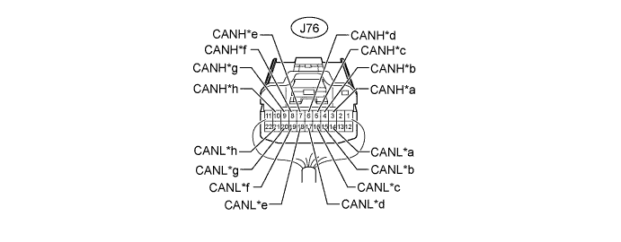
Text in Illustration *a for Electric Vehicle Control ECU assembly (V Bus) *b for Electric Vehicle Control ECU assembly (V Bus) *c for No. 2 Junction Connector (V Bus) *d for ECM (V Bus) *e for ECM (Control Bus) *f for No. 2 Junction Connector (Control Bus) *g for Electric Vehicle Control ECU assembly (Control Bus) *h for Electric Vehicle Control ECU assembly (Control Bus) No. 1 Junction Connector Wiring Color Connect to J76-3 (CANH) R Electric vehicle control ECU assembly (V bus) J76-14 (CANL) G J76-4 (CANH) R Electric vehicle control ECU assembly (V bus) J76-15 (CANL) G J76-5 (CANH) R No. 2 junction connector (V bus) J76-16 (CANL) G J76-6 (CANH) R ECM (V bus) J76-17 (CANL) G J76-7 (CANH) L ECM (Control bus) J76-18 (CANL) G J76-8 (CANH) L No. 2 junction connector (Control bus) J76-19 (CANL) G J76-9 (CANH) L Electric vehicle control ECU assembly (Control bus) J76-20 (CANL) G J76-10 (CANH) L Electric vehicle control ECU assembly (Control bus) J76-21 (CANL) G -
No. 2 Junction Connector
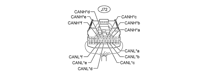
Text in Illustration *a for Airbag ECU Assembly *b for DLC3 *c for No. 3 Junction Connector (V Bus) *d for No. 1 Junction Connector (V Bus) *e for No. 1 Junction Connector (Control Bus) *f for No. 3 Junction Connector (Control Bus) No. 2 Junction Connector Wiring Color Connect to J72-3 (CANH) R Airbag ECU assembly J72-14 (CANL) G J72-4 (CANH) R DLC3 J72-15 (CANL) G J72-5 (CANH) R No. 3 junction connector (V bus) J72-16 (CANL) G J72-6 (CANH) R No. 1 junction connector (V bus) J72-17 (CANL) G J72-7 (CANH) L No. 1 junction connector (Control bus) J72-18 (CANL) G J72-8 (CANH) L No. 3 junction connector (Control bus) J72-19 (CANL) G -
No. 3 Junction Connector
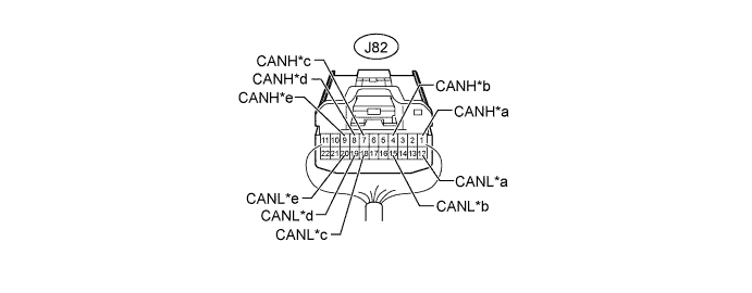
Text in Illustration *a for No. 2 Junction Connector (Control Bus) *b for No. 6 Junction Connector *c for Tachograph Assembly *d for No. 2 Junction Connector (V Bus) *e for No. 4 Junction Connector - - No. 3 Junction Connector Wiring Color Connect to J82-1 (CANH) L No. 2 junction connector (Control bus) J82-12 (CANL) G J82-4 (CANH) L No. 6 junction connector J82-15 (CANL) G J82-7 (CANH) R Tachograph assembly J82-18 (CANL) G J82-8 (CANH) R No. 2 junction connector (V bus) J82-19 (CANL) G J82-9 (CANH) R No. 4 junction connector J82-20 (CANL) G -
No. 4 Junction Connector
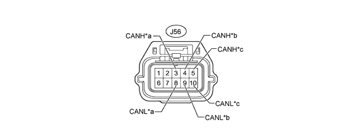
Text in Illustration *a for No. 3 Junction Connector (V Bus) *b for Brake Actuator Assembly (Skid Control ECU) (V Bus) *c for No. 5 Junction Connector - - No. 4 Junction Connector Wiring Color Connect to J56-3 (CANH) R No. 3 junction connector (V bus) J56-8 (CANL) G J56-4 (CANH) R Brake actuator assembly (skid control ECU) (V bus) J56-9 (CANL) G J56-5 (CANH) R No. 5 junction connector J56-10 (CANL) G -
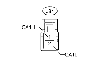
No. 5 Junction Connector
No. 5 Junction Connector Wiring Color Connect to J84-1 (CA1H) R No. 4 junction connector J84-2 (CA1L) G -
No. 6 Junction Connector

Text in Illustration *a for No. 3 Junction Connector (Control Bus) *b for Brake Actuator Assembly (Skid Control ECU) (Control Bus) *c for Combination Meter Assembly - - No. 6 Junction Connector Wiring Color Connect to J58-3 (CANH) L No. 3 junction connector (Control bus) J58-8 (CANL) G J58-4 (CANH) L Brake actuator assembly (skid control ECU) (Control bus) J58-9 (CANL) G J58-5 (CANH) L Combination meter assembly J58-10 (CANL) G -
No. 7 Junction Connector

Text in Illustration *a for ECM (Sub Bus) *b for No. 8 Junction Connector *c for Turbocharger Sub-assembly - - No. 7 Junction Connector Wiring Color Connect to J60-3 (CANH) W ECM (Sub bus) J60-8 (CANL) B J60-4 (CANH) W No. 8 junction connector J60-9 (CANL) B J60-5 (CANH) W Turbocharger sub-assembly J60-10 (CANL) B -
No. 8 Junction Connector

Text in Illustration *a for EGR Valve Assembly *b for No. 7 Junction Connector *c for No. 9 Junction Connector - - No. 8 Junction Connector Wiring Color Connect to J59-3 (CANH) W EGR valve assembly J59-8 (CANL) B J59-4 (CANH) W No. 7 junction connector J59-9 (CANL) B J59-5 (CANH) W No. 9 junction connector J59-10 (CANL) B -
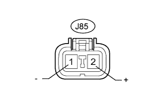
No. 9 Junction Connector
No. 9 Junction Connector Wiring Color Connect to J85-2 (+) W No. 8 junction connector J85-1 (-) B
-
-
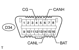
CHECK DLC3
-
Disconnect the cable from the negative (-) battery terminal before measuring the resistances of the CAN main wire and CAN branch wire.
Note
-
After turning the ignition switch off, waiting time may be required before disconnecting the cable from the battery terminal. Therefore, make sure to read the disconnecting the cable from the battery terminal notice before proceeding with work Click here.
-
When disconnecting the cable, some systems need to be initialized after the cable is reconnected Click here.
-
-
Measure the resistance according to the value(s) in the table below.
Terminal No. (Symbol) Wiring Color Switch Condition Specified Condition D34-6 (CANH) - D34-14 (CANL) R - G Ignition switch off 54 to 69 Ω D34-6 (CANH) - D34-4 (CG) R - W-B Ignition switch off 200 Ω or higher D34-14 (CANL) - D34-4 (CG) G - W-B Ignition switch off 200 Ω or higher D34-6 (CANH) - D34-16 (BAT) R - B Ignition switch off 6 kΩ or higher D34-14 (CANL) - D34-16 (BAT) G - B Ignition switch off 6 kΩ or higher
-
-
CHECK ECM
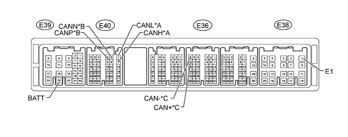
Text in Illustration *A for V Bus *B for Control Bus *C for Sub Bus - -
-
Disconnect the E36, E38, E39 and E40 ECM connectors.
-
Measure the resistance according to the value(s) in the table below.
for V Bus Terminal No. (Symbol) Wiring Color Switch Condition Specified Condition E40-7 (CANH) - E40-1 (CANL) R - G Ignition switch off 108 to 132 Ω E40-7 (CANH) - E38-1 (E1) R - W-B Ignition switch off 200 Ω or higher E40-1 (CANL) - E38-1 (E1) G - W-B Ignition switch off 200 Ω or higher E40-7 (CANH) - E39-23 (BATT) R - G Ignition switch off 6 kΩ or higher E40-1 (CANL) - E39-23 (BATT) G - G Ignition switch off 6 kΩ or higher for Control Bus Terminal No. (Symbol) Wiring Color Switch Condition Specified Condition E40-8 (CANP) - E40-2 (CANN) L - G Ignition switch off 108 to 132 Ω E40-8 (CANP) - E38-1 (E1) L - W-B Ignition switch off 200 Ω or higher E40-2 (CANN) - E38-1 (E1) G - W-B Ignition switch off 200 Ω or higher E40-8 (CANP) - E39-23 (BATT) L - G Ignition switch off 6 kΩ or higher E40-2 (CANN) - E39-23 (BATT) G - G Ignition switch off 6 kΩ or higher for Sub Bus Terminal No. (Symbol) Wiring Color Switch Condition Specified Condition E36-12 (CAN+) - E36-6 (CAN-) W - B Ignition switch off 108 to 132 Ω E36-12 (CAN+) - E38-1 (E1) W - W-B Ignition switch off 200 Ω or higher E36-6 (CAN-) - E38-1 (E1) B - W-B Ignition switch off 200 Ω or higher E36-12 (CAN+) - E39-23 (BATT) W - G Ignition switch off 6 kΩ or higher E36-6 (CAN-) - E39-23 (BATT) B - G Ignition switch off 6 kΩ or higher
-
-
CHECK ELECTRIC VEHICLE CONTROL ECU ASSEMBLY
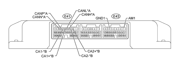
Text in Illustration *A for V Bus *B for Control Bus
-
Disconnect the E41 and E43 electric vehicle control ECU assembly connectors.
-
Measure the resistance according to the value(s) in the table below.
for V Bus Terminal No. (Symbol) Wiring Color Switch Condition Specified Condition E41-4 (CANH) - E41-5 (CANL) R - G Ignition switch off 54 to 69 Ω E41-8 (CANP) - E41-9 (CANN) R - G Ignition switch off 54 to 69 Ω E41-4 (CANH) - E43-5 (GND1) R - W-B Ignition switch off 200 Ω or higher E41-5 (CANL) - E43-5 (GND1) G - W-B Ignition switch off 200 Ω or higher E41-8 (CANP) - E43-5 (GND1) R - W-B Ignition switch off 200 Ω or higher E41-9 (CANN) - E43-5 (GND1) G - W-B Ignition switch off 200 Ω or higher E41-4 (CANH) - E43-1 (AM1) R - B Ignition switch off 6 kΩ or higher E41-5 (CANL) - E43-1 (AM1) G - B Ignition switch off 6 kΩ or higher E41-8 (CANP) - E43-1 (AM1) R - B Ignition switch off 6 kΩ or higher E41-9 (CANN) - E43-1 (AM1) G - B Ignition switch off 6 kΩ or higher for Control Bus Terminal No. (Symbol) Wiring Color Switch Condition Specified Condition E41-6 (CA1+) - E41-7 (CA1-) L - G Ignition switch off 54 to 69 Ω E41-2 (CA2+) - E41-3 (CA2-) L - G Ignition switch off 54 to 69 Ω E41-6 (CA1+) - E43-5 (GND1) L - W-B Ignition switch off 200 Ω or higher E41-7 (CA1-) - E43-5 (GND1) G - W-B Ignition switch off 200 Ω or higher E41-2 (CA2+) - E43-5 (GND1) L - W-B Ignition switch off 200 Ω or higher E41-3 (CA2-) - E43-5 (GND1) G - W-B Ignition switch off 200 Ω or higher E41-6 (CA1+) - E43-1 (AM1) L - B Ignition switch off 6 kΩ or higher E41-7 (CA1-) - E43-1 (AM1) G - B Ignition switch off 6 kΩ or higher E41-2 (CA2+) - E43-1 (AM) L - B Ignition switch off 6 kΩ or higher E41-3 (CA2-) - E43-1 (AM1) G - B Ignition switch off 6 kΩ or higher
-
-
CHECK BRAKE ACTUATOR ASSEMBLY (SKID CONTROL ECU)
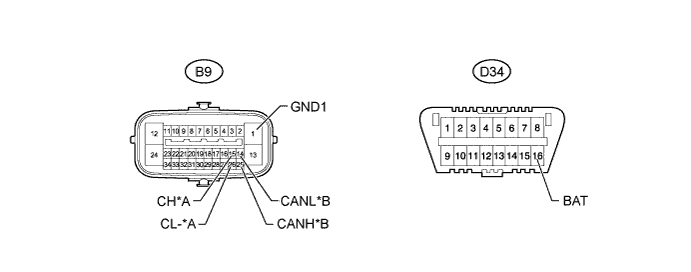
Text in Illustration *A for V Bus *B for Control Bus
-
Disconnect the B9 brake actuator assembly (skid control ECU) connector.
-
Measure the resistance according to the value(s) in the table below.
for V Bus Terminal No. (Symbol) Wiring Color Switch Condition Specified Condition B9-15 (CH) - B9-26 (CL-) R - G Ignition switch off 54 to 69 Ω B9-15 (CH) - B9-1 (GND1) R - W-B Ignition switch off 200 Ω or higher B9-26 (CL-) - B9-1 (GND1) G - W-B Ignition switch off 200 Ω or higher B9-15 (CH) - D34-16 (BAT) R - B Ignition switch off 6 kΩ or higher B9-26 (CL-) - D34-16 (BAT) G - B Ignition switch off 6 kΩ or higher for Control Bus Terminal No. (Symbol) Wiring Color Switch Condition Specified Condition B9-25 (CANH) - B9-14 (CANL) L - G Ignition switch off 54 to 69 Ω B9-25 (CANH) - B9-1 (GND1) L - W-B Ignition switch off 200 Ω or higher B9-14 (CANL) - B9-1 (GND1) G - W-B Ignition switch off 200 Ω or higher B9-25 (CANH) - D34-16 (BAT) L - B Ignition switch off 6 kΩ or higher B9-14 (CANL) - D34-16 (BAT) G - B Ignition switch off 6 kΩ or higher
-
-
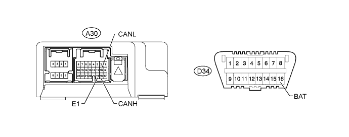
CHECK AIRBAG ECU ASSEMBLY
-
Disconnect the A30 airbag ECU assembly connector Click here.
-
Measure the resistance according to the value(s) in the table below.
Terminal No. (Symbol) Wiring Color Switch Condition Specified Condition A30-18 (CANH) - A30-10 (CANL) R - G Ignition switch off 54 to 69 Ω A30-18 (CANH) - A30-19 (E1) R - W-B Ignition switch off 200 Ω or higher A30-10 (CANL) - A30-19 (E1) G - W-B Ignition switch off 200 Ω or higher A30-18 (CANH) - D34-16 (BAT) R - B Ignition switch off 6 kΩ or higher A30-10 (CANL) - D34-16 (BAT) G - B Ignition switch off 6 kΩ or higher
-
-
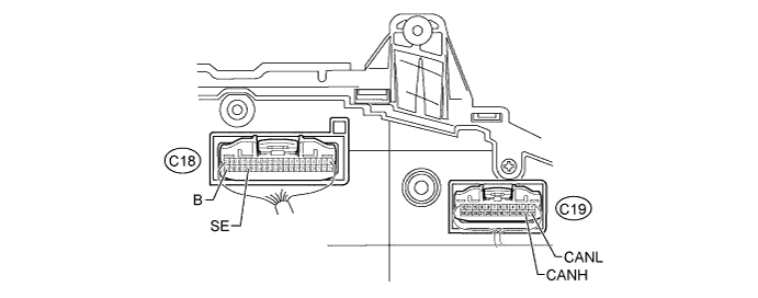
CHECK COMBINATION METER ASSEMBLY
-
Disconnect the C18 and C19 combination meter assembly connectors.
-
Measure the resistance according to the value(s) in the table below.
Terminal No. (Symbol) Wiring Color Switch Condition Specified Condition C19-14 (CANH) - C19-13 (CANL) L - G Ignition switch off 108 to 132 Ω C19-14 (CANH) - C18-36 (SE) L - BR Ignition switch off 200 Ω or higher C19-13 (CANL) - C18-36 (SE) G - BR Ignition switch off 200 Ω or higher C19-14 (CANH) - C18-40 (B) L - B Ignition switch off 6 kΩ or higher C19-13 (CANL) - C18-40 (B) G - B Ignition switch off 6 kΩ or higher
-
-
CHECK TURBOCHARGER SUB-ASSEMBLY
-
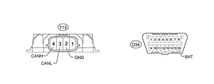
Disconnect the T13 turbocharger sub-assembly connector.
-
Measure the resistance according to the value(s) in the table below.
Terminal No. (Symbol) Wiring Color Switch Condition Specified Condition T13-4 (CANH) - T13-3 (CANL) W - B Ignition switch off 54 to 69 Ω T13-4 (CANH) - T13-2 (GND) W - W-B Ignition switch off 200 Ω or higher T13-3 (CANL) - T13-2 (GND) B - W-B Ignition switch off 200 Ω or higher T13-4 (CANH) - D34-16 (BAT) W - B Ignition switch off 6 kΩ or higher T13-3 (CANL) - D34-16 (BAT) B - B Ignition switch off 6 kΩ or higher
-
-
CHECK EGR VALVE ASSEMBLY
-
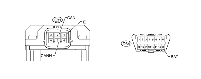
Disconnect the E31 EGR valve assembly connector.
-
Measure the resistance according to the value(s) in the table below.
Terminal No. (Symbol) Wiring Color Switch Condition Specified Condition E31-5 (CANH) - E31-2 (CANL) W - B Ignition switch off 54 to 69 Ω E31-5 (CANH) - E31-1 (E) W - W-B Ignition switch off 200 Ω or higher E31-2 (CANL) - E31-1 (E) B - W-B Ignition switch off 200 Ω or higher E31-5 (CANH) - D34-16 (BAT) W - B Ignition switch off 6 kΩ or higher E31-2 (CANL) - D34-16 (BAT) B - B Ignition switch off 6 kΩ or higher
-