INSTRUMENT PANEL SAFETY PAD REMOVAL

-
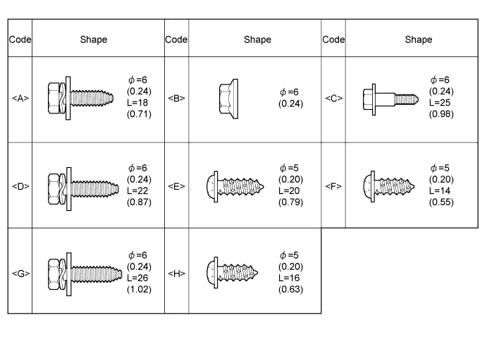
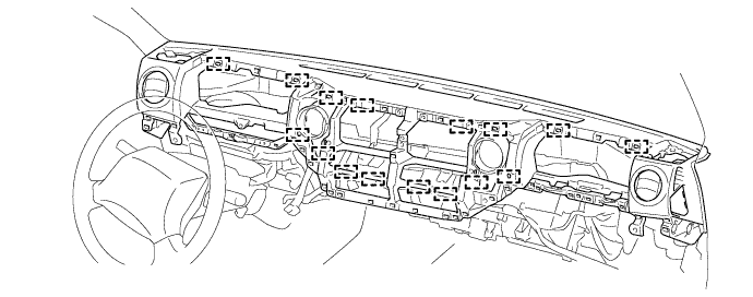
BOLTS, SCREWS AND NUTS TABLE
Tech Tips
All bolts, screws and nuts relevant to installing and removing the instrument panel are shown, along with their alphabetic codes, in the table below.
-
PRECAUTION
Note
After turning the ignition switch off, waiting time may be required before disconnecting the cable from the negative (-) battery terminal. Therefore, make sure to read the disconnecting the cable from the negative (- ) battery terminal notices before proceeding with work Click here.
-
DISCONNECT CABLE FROM NEGATIVE BATTERY TERMINAL
Note
When disconnecting the cable some systems need to be initialized after the cable is reconnected Click here.
-
REMOVE ASSIST GRIP PLUG
-
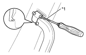
Text in Illustration *1 Protective Tape Using a screwdriver, detach the 3 claws and remove the assist grip plug.
Tech Tips
-
Use the same procedure for the other assist grip plug.
-
Tape the screwdriver tip before use.
-
-
-
REMOVE NO. 2 ASSIST GRIP ASSEMBLY RH
-
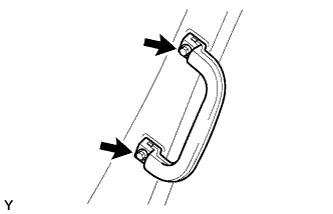
Remove the 2 screws and No. 2 assist grip assembly RH.
-
-
REMOVE NO. 2 ASSIST GRIP ASSEMBLY LH
Tech Tips
Use the same procedure described for the RH side.
-
REMOVE FRONT PILLAR GARNISH RH
-
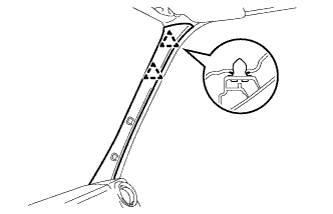
Detach the 2 clips and remove the front pillar garnish RH.
-
-
REMOVE FRONT PILLAR GARNISH LH
Tech Tips
Use the same procedure described for the RH side.
-
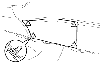
REMOVE LOWER INSTRUMENT PANEL FINISH PANEL SUB-ASSEMBLY LH
-
Remove the 2 clips.
-
Detach the 3 clips and remove the lower instrument panel finish panel sub-assembly LH.
-
Disconnect each connector.
-
-
REMOVE LOWER INSTRUMENT PANEL FINISH PANEL SUB-ASSEMBLY RH
-
Detach the 5 clips and remove the lower instrument panel finish panel sub-assembly.
-
Disconnect each connector.
-
-
REMOVE LOWER STEERING COLUMN COVER
-
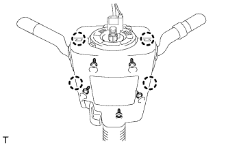
Remove the 5 screws.
-
Disengage the 4 claws and remove the lower steering column cover.
-
-
REMOVE UPPER STEERING COLUMN COVER
-
Disengage the 3 claws and separate the steering column cover plate.
-
Remove the upper steering column cover from the steering column.
-
-
REMOVE CENTER INSTRUMENT CLUSTER FINISH PANEL SUB-ASSEMBLY
-
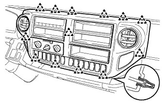
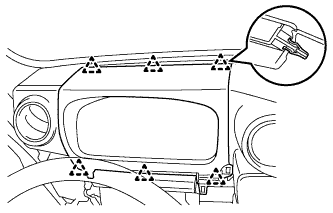
Detach the 13 clips and remove the center instrument cluster finish panel sub-assembly.
-
Disconnect each connector.
-
-
REMOVE NO. 1 INSTRUMENT CLUSTER FINISH PANEL
-
Detach the 6 clips and remove the No. 1 instrument cluster finish panel.
-
-
REMOVE COMBINATION METER ASSEMBLY
-
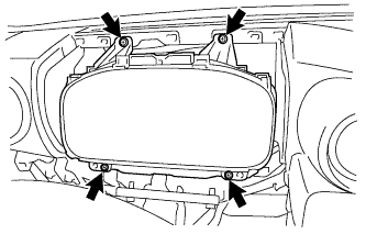
Remove the 4 screws and remove the combination meter assembly.
-
Disconnect each connector.
-
-
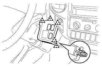
REMOVE INSTRUMENT PANEL BOX
-
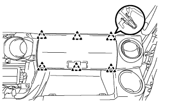
Detach the 6 clips and remove the instrument panel box.
-
-
REMOVE INSTRUMENT PANEL BOX HOLDER
-
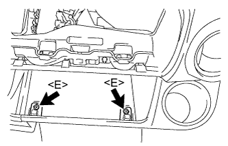
Remove the 2 screws <E> and 2 instrument panel box holders.
-
-
REMOVE LOWER INSTRUMENT COVER
-
Detach the 4 clips and remove the lower instrument cover.
-
-
REMOVE LOWER INSTRUMENT PANEL
-
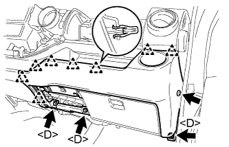
Remove the clip.
-
Remove the 3 bolts <D>.
-
Detach the 8 clips and remove the lower instrument panel.
-
-
REMOVE FUSE BOX OPENING COVER
-
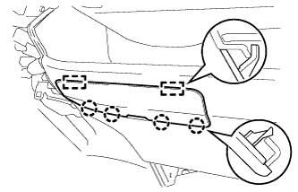
Detach the 4 claws and 2 guides and remove the fuse box opening cover.
-
-
REMOVE LOWER INSTRUMENT COVER SUB-ASSEMBLY
-
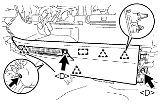
Remove the clip.
-
Remove the 2 bolts <D>.
-
Detach the 4 clips and guide and remove the lower instrument cover sub-assembly.
-
-
REMOVE NO. 1 INSTRUMENT PANEL BOX
-
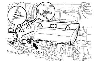
Remove the bolt <G>.
-
Detach the 4 clips, claw and guide and remove the No. 1 instrument panel box.
-
Detach the 2 clamps.
-
-
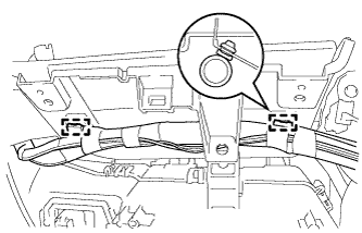
REMOVE NO. 2 INSTRUMENT PANEL BOX
-
Remove the bolt <G>.
-
Detach the 3 clips and 2 guides remove the No. 2 instrument panel box.
-
-
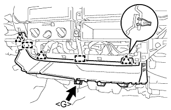
REMOVE NO. 1 INSTRUMENT PANEL SPEAKER PANEL SUB-ASSEMBLY
-
Detach the 2 clips and 2 guides and remove the No. 1 instrument panel speaker panel sub-assembly.
-
-
REMOVE NO. 2 INSTRUMENT PANEL SPEAKER PANEL SUB-ASSEMBLY
Tech Tips
Use the same procedure described for the No. 1 instrument panel speaker panel sub-assembly.
-
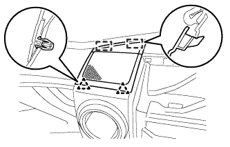
REMOVE FRONT NO. 1 SPEAKER ASSEMBLY
-
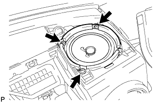
Remove the 3 screws.
-
Disconnect the connector and remove the front No. 1 speaker assembly.
Tech Tips
Use the same procedure for the other front No. 1 speaker assembly.
-
-
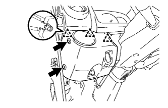
REMOVE OIL RESERVOIR TANK COVER LH
-
Disengage the 4 claws and 3 guides and remove the oil reservoir tank cover LH.
-
-
REMOVE WINDSHIELD WASHER JAR CAP
-
Remove the front washer tank cap.
-
-
DISCONNECT FRONT WASHER TANK CAP
-
Disconnect the front washer tank cap from the instrument panel sub-assembly.
-
-
REMOVE STEREO OPENING COVER
-
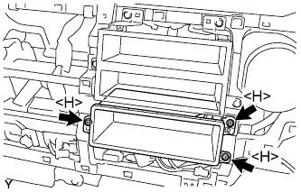
Remove the 3 screws <H> and stereo opening cover.
-
-
REMOVE STEREO OPENING COVER
-
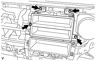
Remove the 4 bolts and stereo opening cover.
-
-
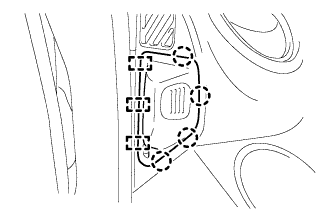
REMOVE INSTRUMENT PANEL JUNCTION BLOCK ASSEMBLY
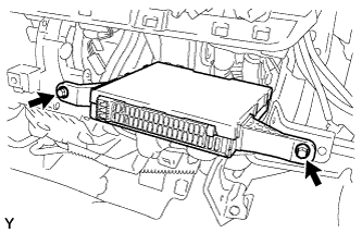
-
Remove the 2 bolts.
-
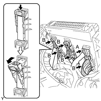
Disconnect the A connector from the rear of the instrument panel junction block assembly.
-
Disconnect the 5 B connectors from the rear of the instrument panel junction block assembly as shown in the illustration, and remove the instrument panel junction block assembly.
-
-
REMOVE HEATER CONTROL AND ACCESSORY ASSEMBLY
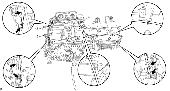
Text in Illustration *1 Air Inlet Damper Control Cable Sub-assembly *2 No. 1 Heater Control Cable Sub-assembly *3 Airmix Damper Control Cable Sub-assembly - -
-
Separate the air inlet damper control cable.
-
Disconnect the outer cable from the 2 clamps and the cable clip.
-
Disconnect the inner cable and separate the air inlet damper control cable.
-
-
Separate the No. 1 heater control cable sub-assembly.
-
Disconnect the outer cable from the cable clip.
-
Disconnect the inner cable and separate the No. 1 heater control cable sub-assembly.
-
-
Separate the airmix damper control cable sub-assembly.
-
Disconnect the outer cable from the cable clip.
-
Disconnect the inner cable and separate the airmix damper control cable sub-assembly.
-
-
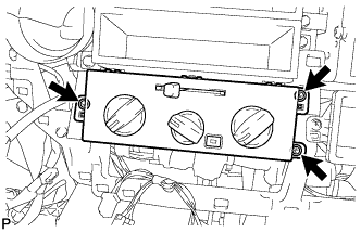
Remove the 3 screws and the heater control and accessory assembly.
-
-
REMOVE INSTRUMENT PANEL SUB-ASSEMBLY
-
Disconnect each connector.
-
Detach each clamps.
-
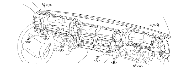
Remove the 4 bolts <A> and 2 bolts <C> and 2 nuts <B>.
-
Detach the 3 guides and remove the instrument panel sub-assembly.
-