OUTER MIRROR SWITCH INSPECTION

-
INSPECT OUTER MIRROR SWITCH ASSEMBLY
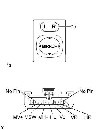
Text in Illustration *a Component without harness connected
(Outer Mirror Switch Assembly)
*b Select Switch
-
Inspect the outer mirror switch assembly.
-
Select "L" on the select switch.
-
Measure the resistance according to the value(s) in the table below.
Standard Resistance Tester Connection Switch Condition Specified Condition 4 (VL) - 8 (MV+)
6 (MH+) - 7 (MSW)
UP Pressed Below 1 Ω Not pressed 10 kΩ or higher 4 (VL) - 7 (MSW)
6 (MH+) - 8 (MV+)
DOWN Pressed Below 1 Ω Not pressed 10 kΩ or higher 5 (HL) - 8 (MV+)
6 (MH+) - 7 (MSW)
LEFT Pressed Below 1 Ω Not pressed 10 kΩ or higher 5 (HL) - 7 (MSW)
6 (MH+) - 8 (MV+)
RIGHT Pressed Below 1 Ω Not pressed 10 kΩ or higher If the result is not as specified, replace the outer mirror switch assembly.
-
Select "R" on the select switch.
-
Measure the resistance according to the value(s) in the table below.
Standard Resistance Tester Connection Switch Condition Specified Condition 3 (VR) - 8 (MV+)
6 (MH+) - 7 (MSW)
UP Pressed Below 1 Ω Not pressed 10 kΩ or higher 3 (VR) - 7 (MSW)
6 (MH+) - 8 (MV+)
DOWN Pressed Below 1 Ω Not pressed 10 kΩ or higher 2 (HR) - 8 (MV+)
6 (MH+) - 7 (MSW)
LEFT Pressed Below 1 Ω Not pressed 10 kΩ or higher 2 (HR) - 7 (MSW)
6 (MH+) - 8 (MV+)
RIGHT Pressed Below 1 Ω Not pressed 10 kΩ or higher If the result is not as specified, replace the outer mirror switch assembly.
-
-