OUTER REAR VIEW MIRROR INSPECTION

-
INSPECT OUTER REAR VIEW MIRROR LH
-
w/ Mirror Heater:
-
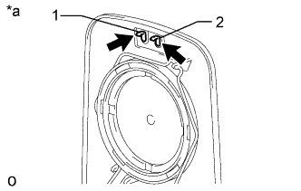
Text in Illustration *a Component without harness connected
(Outer Rear View Mirror LH)
Apply battery voltage and check the operation of the mirror heater.
OK Measurement Condition Specified Condition 1 - 2 Mirror becomes warm Tech Tips
It will take a short amount of time for the mirror to become warm.
If the result is not as specified, replace the outer rear view mirror LH.
-
-
-
INSPECT OUTER REAR VIEW MIRROR RH
-
w/ Mirror Heater:
-
Text in Illustration *a Component without harness connected
(Outer Rear View Mirror RH)
Apply battery voltage and check the operation of the mirror heater.
OK Measurement Condition Specified Condition 1 - 2 Mirror becomes warm Tech Tips
It will take a short amount of time for the mirror to become warm.
If the result is not as specified, replace the outer rear view mirror RH.
-
-
-
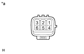
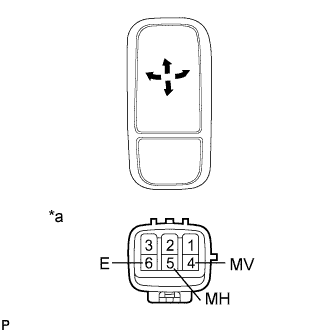
INSPECT OUTER REAR VIEW MIRROR SUB-ASSEMBLY LH
-
w/ Power Mirror Control System:
-

Text in Illustration *a Component without harness connected
(Outer Rear View Mirror Sub-assembly LH)
Apply battery voltage and check the operation of the mirror.
OK Measurement Condition Specified Condition Battery positive (+) → Terminal 4 (MV)
Battery negative (-) → Terminal 6 (E)
Turns upward Battery negative (-) → Terminal 4 (MV)
Battery positive (+) → Terminal 6 (E)
Turns downward Battery positive (+) → Terminal 5 (MH)
Battery negative (-) → Terminal 6 (E)
Turns left Battery negative (-) → Terminal 5 (MH)
Battery positive (+) → Terminal 6 (E)
Turns right If the result is not as specified, replace the outer rear view mirror sub-assembly LH.
-
Text in Illustration *a Component without harness connected
(Outer Rear View Mirror Sub-assembly LH)
Apply battery voltage and check the operation of the mirror heater.
OK Measurement Condition Specified Condition Battery positive (+) → Terminal 1
Battery negative (-) → Terminal 3
Mirror becomes warm Tech Tips
It will take a short amount of time for the mirror to become warm.
If the result is not as specified, check the outer rear view mirror LH.
If the result is not as specified, replace the outer rear view mirror sub-assembly LH.
-
-
w/o Power Mirror Control System:
-
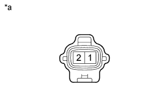
Text in Illustration *a Component without harness connected
(Outer Rear View Mirror Sub-assembly LH)
Apply battery voltage and check the operation of the mirror heater.
OK Measurement Condition Specified Condition Battery positive (+) → Terminal 1
Battery negative (-) → Terminal 2
Mirror becomes warm Tech Tips
It will take a short amount of time for the mirror to become warm.
If the result is not as specified, check the outer rear view mirror LH.
If the result is not as specified, replace the outer rear view mirror sub-assembly LH.
-
-
-
INSPECT OUTER REAR VIEW MIRROR SUB-ASSEMBLY RH
-
w/ Power Mirror Control System:
-
Text in Illustration *a Component without harness connected
(Outer Rear View Mirror Sub-assembly RH)
Apply battery voltage and check the operation of the mirror.
OK Measurement Condition Specified Condition Battery positive (+) → Terminal 4 (MV)
Battery negative (-) → Terminal 6 (E)
Turns upward Battery negative (-) → Terminal 4 (MV)
Battery positive (+) → Terminal 6 (E)
Turns downward Battery positive (+) → Terminal 5 (MH)
Battery negative (-) → Terminal 6 (E)
Turns left Battery negative (-) → Terminal 5 (MH)
Battery positive (+) → Terminal 6 (E)
Turns right If the result is not as specified, replace the outer rear view mirror sub-assembly RH.
-
Text in Illustration *a Component without harness connected
(Outer Rear View Mirror Sub-assembly RH)
Apply battery voltage and check the operation of the mirror heater.
OK Measurement Condition Specified Condition Battery positive (+) → Terminal 1
Battery negative (-) → Terminal 3
Mirror becomes warm Tech Tips
It will take a short amount of time for the mirror to become warm.
If the result is not as specified, check the outer rear view mirror RH.
If the result is not as specified, replace the outer rear view mirror sub-assembly RH.
-
-
w/o Power Mirror Control System:
-
Text in Illustration *a Component without harness connected
(Outer Rear View Mirror Sub-assembly RH)
Apply battery voltage and check the operation of the mirror heater.
OK Measurement Condition Specified Condition Battery positive (+) → Terminal 1
Battery negative (-) → Terminal 2
Mirror becomes warm Tech Tips
It will take a short amount of time for the mirror to become warm.
If the result is not as specified, check the outer rear view mirror RH.
If the result is not as specified, replace the outer rear view mirror sub-assembly RH.
-
-
-
INSPECT OUTER REAR VIEW MIRROR STAY SUB-ASSEMBLY LH
-
w/ Power Mirror Control System:
-
Measure the resistance according to the value(s) in the table below.
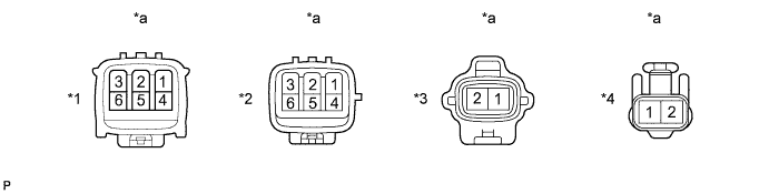
Text in Illustration *1 Connector A *2 Connector B *3 Connector C *4 Connector D *a Component without harness connected
(Outer Rear View Mirror Stay Sub-assembly LH)
- - Standard Resistance Tester Connection Condition Specified Condition A1 - B3 Always Below 1 Ω A2 - B2 Always Below 1 Ω A3 - B1 Always Below 1 Ω A4 - B6 Always Below 1 Ω A5 - B5 Always Below 1 Ω A6 - B4 Always Below 1 Ω C1 - D1 Always Below 1 Ω C2 - D2 Always Below 1 Ω If the result is not as specified, replace the outer rear view mirror stay sub-assembly LH.
-
-
w/o Power Mirror Control System:
Measure the resistance according to the value(s) in the table below.

Text in Illustration *1 Connector A *2 Connector B *a Component without harness connected
(Outer Rear View Mirror Stay Sub-assembly LH)
- - Standard Resistance Tester Connection Condition Specified Condition A1 - B1 Always Below 1 Ω A2 - B2 Always Below 1 Ω If the result is not as specified, replace the outer rear view mirror stay sub-assembly LH.
-
-
INSPECT OUTER REAR VIEW MIRROR STAY SUB-ASSEMBLY RH
-
w/ Power Mirror Control System:
-
Measure the resistance according to the value(s) in the table below.
Text in Illustration *1 Connector A *2 Connector B *3 Connector C *4 Connector D *a Component without harness connected
(Outer Rear View Mirror Stay Sub-assembly RH)
- - Standard Resistance Tester Connection Condition Specified Condition A1 - B3 Always Below 1 Ω A2 - B2 Always Below 1 Ω A3 - B1 Always Below 1 Ω A4 - B6 Always Below 1 Ω A5 - B5 Always Below 1 Ω A6 - B4 Always Below 1 Ω C1 - D1 Always Below 1 Ω C2 - D2 Always Below 1 Ω If the result is not as specified, replace the outer rear view mirror stay sub-assembly RH.
-
-
w/o Power Mirror Control System:
Measure the resistance according to the value(s) in the table below.
Text in Illustration *1 Connector A *2 Connector B *a Component without harness connected
(Outer Rear View Mirror Stay Sub-assembly RH)
- - Standard Resistance Tester Connection Condition Specified Condition A1 - B1 Always Below 1 Ω A2 - B2 Always Below 1 Ω If the result is not as specified, replace the outer rear view mirror stay sub-assembly RH.
-