WINDSHIELD GLASS INSTALLATION

-
INSTALL WINDSHIELD GLASS STOPPER
-
Apply Primer G to the windshield glass where the windshield stoppers will be installed.
Note
-
Allow the primer to dry for 3 minutes or more.
-
Throw away any leftover primer.
-
Do not apply too much primer.
-
-
Remove the peeling paper from 2 new windshield stoppers.
-
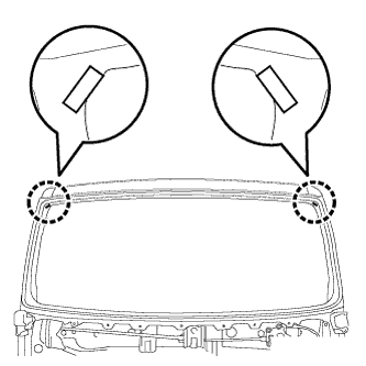
Install the 2 windshield glass stoppers to the windshield glass at the locations shown in the illustration.
-
-
INSTALL NO. 2 WINDSHIELD GLASS STOPPER
-
Apply Primer G to the windshield glass where the No. 2 windshield stoppers will be installed.
Note
-
Allow the primer to dry for 3 minutes or more.
-
Throw away any leftover primer.
-
Do not apply too much primer.
-
-
Remove the peeling paper from a new No. 2 windshield stopper.
-
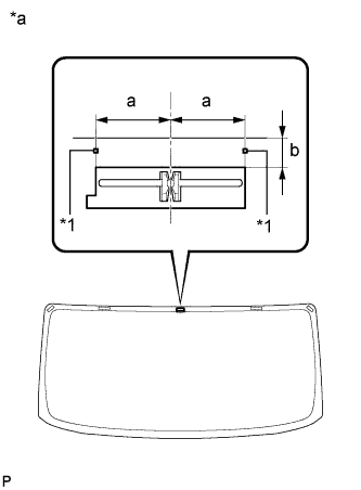
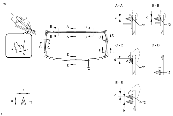
Text in Illustration *1 Ceramic Notch *a Backside Install the No. 2 windshield glass stopper to the windshield glass as shown in the illustration.
Standard Area Specified Condition a 25.0 mm (0.984 in.) b 11.9 mm (0.469 in.)
-
-
INSTALL NO. 1 WINDSHIELD GLASS STOPPER
-
Apply Primer G to the windshield glass where the stoppers will be installed.
Note
-
Allow the primer to dry for 3 minutes or more.
-
Throw away any leftover primer.
-
Do not apply too much primer.
-
-
Remove the peeling paper from 2 new No. 1 windshield glass stoppers.
-
Install the 2 No. 1 windshield glass stoppers to the windshield glass as shown in the illustration.
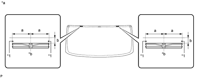
Text in Illustration *1 Ceramic Notch - - *a Backside *b Center Standard Area Specified Condition a 36.0 mm (1.42 in.) b 9.5 mm (0.374 in.)
-
-
INSTALL WINDSHIELD GLASS RETAINER
-
Apply Primer G to the windshield glass where the windshield glass retainers will be installed.
Note
-
Allow the primer to dry for 3 minutes or more.
-
Throw away any leftover primer.
-
Do not apply too much primer.
-
-
Remove the peeling paper from 2 new windshield glass retainers.
-
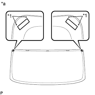
Text in Illustration *1 Ceramic Notch *a Backside Install the 2 windshield glass retainers to the windshield glass as shown in the illustration.
-
-
INSTALL WINDSHIELD OUTER UPPER MOULDING
-
Apply primer to the windshield glass where the windshield outer upper moulding will be installed.
Note
-
Allow the primer to dry for 3 minutes or more.
-
Throw away any leftover primer.
-
Do not apply too much primer.
-
-
Remove the peeling paper from a new windshield outer upper moulding.
-
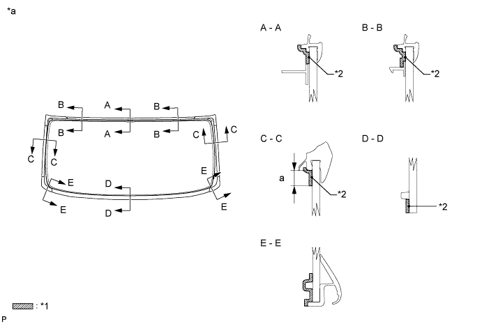
Install the windshield outer upper moulding to the windshield glass as shown in the illustration.
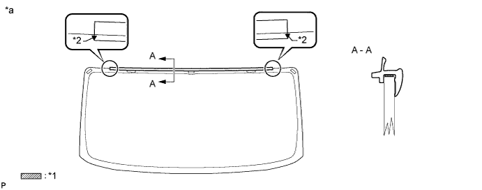
Text in Illustration *1 Double-sided Tape *2 Ceramic Notch *a Backside - -
-
-
INSTALL WINDOW GLASS ADHESIVE DAM
-
Apply Primer G to the windshield glass where the windshield glass adhesive dam will be installed.
Note
-
Allow the primer to dry for 3 minutes or more.
-
Throw away any leftover primer.
-
Do not apply too much primer.
-
-
Remove the peeling paper from a new windshield glass adhesive dam.
-
Install the windshield glass adhesive dam to the windshield glass as shown in the illustration.
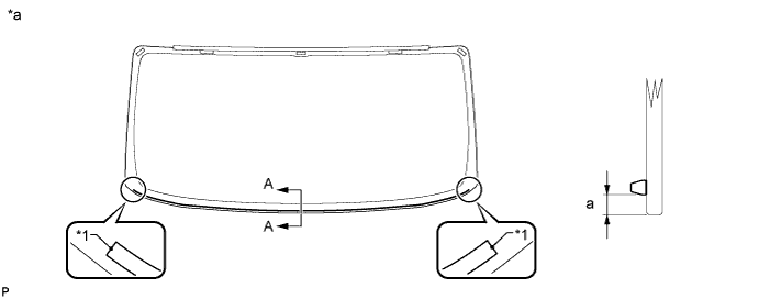
Text in Illustration *1 Ceramic Notch - - *a Backside - - Standard Area Specified Condition a 9.0 mm (0.354 in.)
-
-
INSTALL WINDSHIELD OUTSIDE MOULDING LH
-
Apply Primer G to the windshield glass where the windshield outside moulding LH will be installed.
Note
-
Allow the primer to dry for 3 minutes or more.
-
Throw away any leftover primer.
-
Do not apply too much primer.
-
-
Remove the peeling paper from a new windshield outside moulding LH.
-
Install the windshield outside moulding LH to the windshield glass as shown in the illustration.
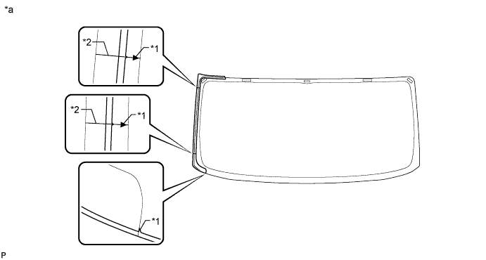
Text in Illustration *1 Ceramic Notch *2 Line *a Backside - -
-
-
INSTALL WINDSHIELD OUTSIDE MOULDING RH
Tech Tips
Use the same procedure described for the LH side.
-
INSTALL WINDSHIELD GLASS
-
Position the windshield glass.
-
Using suction cups, place the windshield glass in the correct position.
-
Check that the entire contact surface of the windshield glass rim is perfectly even.
-
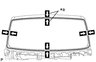
Text in Illustration *a Matchmark Place matchmarks on the windshield glass and vehicle body at the locations indicated in the illustration.
Note
Check that each stopper is attached to the vehicle body correctly.
Tech Tips
-
Placing matchmarks is only necessary when installing new windshield glass. When reinstalling the used windshield glass, matchmarks should already be present.
-
When reusing the windshield glass, check and correct the matchmark positions.
-
-
-
Using suction cups, remove the windshield glass.
-
Using a brush, apply Primer M to the exposed part of the vehicle body.
Note
-
Allow the primer to dry for 3 minutes or more.
-
Do not apply primer to the adhesive.
-
Throw away any leftover primer.
-
Do not apply too much primer.
-
-
Using a brush or sponge, apply Primer G to the contact surface of the windshield glass.
Text in Illustration *1 Primer G *2 Adhesive Center Line *a Backside - - Standard Area Specified Condition a 11.0 mm (0.433 in.) Tech Tips
If the primer is applied to an area that is not specified, apply non-residue solvent to a clean cloth and wipe off the excess primer before it dries.
-
Apply adhesive to the windshield glass.
Adhesive Toyota Genuine Windshield Glass Adhesive or equivalent
-
Cut off the tip of a cartridge nozzle as shown in the illustration.
Text in Illustration *1 Adhesive *2 Adhesive Center Line *a Backside - - Tech Tips
After cutting off the tip, use all adhesive within the time written in the table below.
Usage Time Frame Temperature Usage Time Frame 35°C (95°F) 15 minutes 20°C (68°F) 1 hour 40 minutes 5°C (41°F) 8 hours
-
-
Load a sealer gun with the cartridge.
-
Apply adhesive to the windshield glass as shown in the illustration.
Standard Area Specified Condition a 12.0 mm (0.472 in.) b 8.0 mm (0.315 in.) c 3.0 mm (0.118 in.) d 4.0 mm (0.157 in.) -
Install the windshield glass to the vehicle body.
-
Text in Illustration *a Matchmark Using suction cups, position the windshield glass so that the matchmarks are aligned. Press it in gently along the rim.
-
Lightly press the outer surface of the windshield glass to ensure that it is securely attached to the vehicle body.
Note
-
Check that each stopper is attached to the vehicle body correctly.
-
Check that the vehicle body and windshield glass have a small gap between them.
-
-
Using a scraper, remove any excess or protruding adhesive.
Tech Tips
Apply adhesive to any areas where the amount of adhesive is inadequate.
-
Hold the windshield glass in place securely with protective tape or equivalent until the adhesive hardens.
Note
Do not drive the vehicle for the amount of time written in the table below.
Minimum Time Temperature Minimum Time Prior to Driving Vehicle 35°C (95°F) 1 hour 30 minutes 20°C (68°F) 5 hours 5°C (41°F) 24 hours
-
-
-
CHECK FOR LEAKS AND REPAIR
-
Conduct a leak test after the adhesive has completely hardened.
-
If there are any leaks, seal them with auto glass sealer.
-
-
INSTALL FRONT PANEL COVER SUB-ASSEMBLY
-
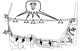
Attach the 5 clips and install the outer cowl top panel sub-assembly.
-
Install the 5 bolts and 4 screws.
- Torque:
- 8.5 N*m { 87 kgf*cm, 75 in.*lbf }
-
Connect the washer hose.
Text in Illustration 
Bolt 
Screw 
Washer hose
-
-
INSTALL HEADLIGHT ASSEMBLY LH
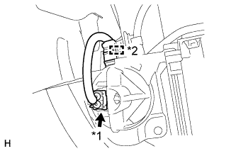
Text in Illustration *1 Front Turn Signal Light Connector *2 Clamp
-
Connect the connectors and attach the clamps.
Tech Tips
Before installing the headlight assembly LH, disconnect the front turn signal light connector and detach the clamp shown in the illustration to allow for easy installation of the headlight assembly LH. Once the headlight assembly LH is installed, reconnect the front turn signal light connector and attach the clamp shown in the illustration from the rear.
-
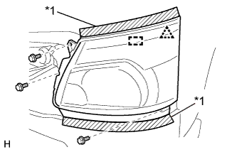
Text in Illustration *1 Protective Tape Put protective tape around the headlight assembly LH.
-
Attach the clip and guide to install the headlight assembly LH.
-
Install the 3 bolts.
- Torque:
- 5.0 N*m { 51 kgf*cm, 44 in.*lbf }
-
-
INSTALL HEADLIGHT ASSEMBLY RH
Tech Tips
Use the same procedure described for the LH side.
-
INSTALL FRONT WIPER SHAFT PACKING
-
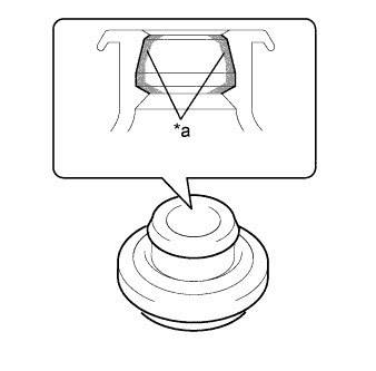
Text in Illustration *a Lip Position 
MP grease Apply MP grease to the entire surface of the front wiper shaft packing lip.
Tech Tips
Make sure that the hole does not get clogged with MP grease and the grooves on the lip are filled with MP grease.
-
for Driver Side:
-
Install the front wiper shaft packing.
-
-
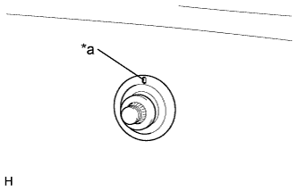
Text in Illustration *a Alignment Mark for Front Passenger Side:
-
Position the alignment mark upwards and install the front wiper shaft packing.
-
-
-
INSTALL FRONT WIPER ARM LH
-
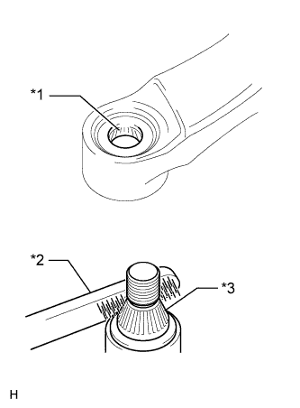
Text in Illustration *1 Wiper Arm Serrations *2 Wire Brush *3 Wiper Pivot Serrations Operate the wiper and stop the front wiper motor and bracket assembly at the automatic stop position.
-
Clean the wiper arm serrations to remove any burrs, dirt, etc.
Note
Do not grind down the wiper arm serrations.
-
When reusing the front wiper motor and bracket assembly:
-
Clean the wiper pivot serrations with a wire brush.
-
-
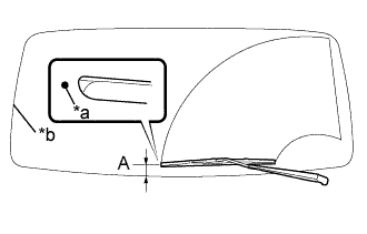
Text in Illustration *a Ceramic Dot *b Edge of lower windshield outside moulding Position the blade tip within the range shown in the illustration.
Tech Tips
The blade position is indicated by the mark on the glass.
Standard Area Standard Condition A 46.3 mm (1.82 in.) -
Install the front wiper arm LH with the nut.
- Torque:
- 25 N*m { 255 kgf*cm, 18 ft.*lbf }
Tech Tips
Hold the arm hinge by hand when tightening the nut.
-
-
INSTALL FRONT WIPER ARM RH
-
Text in Illustration *1 Wiper Arm Serrations *2 Wire Brush *3 Wiper Pivot Serrations Operate the wiper and stop the front wiper motor and bracket assembly at the automatic stop position.
-
Clean the wiper arm serrations to remove any burrs, dirt, etc.
Note
Do not grind down the wiper arm serrations.
-
When reusing the front wiper motor and bracket assembly:
-
Clean the wiper pivot serrations with a wire brush.
-
-
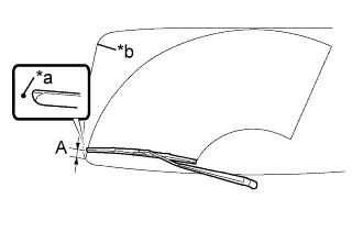
Text in Illustration *a Ceramic Dot *b Edge of lower windshield outside moulding Position the blade tip within the range shown in the illustration.
Tech Tips
The blade position is indicated by the mark on the glass.
Standard Area Standard Condition A 50.3 mm (1.98 in.) -
Install the front wiper arm RH with the nut.
- Torque:
- 25 N*m { 255 kgf*cm, 18 ft.*lbf }
Tech Tips
Hold the arm hinge by hand when tightening the nut.
-
-
INSTALL FRONT WIPER ARM HEAD CAP
-
Attach the 3 claws and install the front wiper arm head cap.
Tech Tips
Use the same procedure for both side front wiper arm head cap.
-
-
INSTALL FRONT SIDE PANEL SUB-ASSEMBLY LH
-
Attach the 5 clips to install the front side panel sub-assembly LH.
-
-
INSTALL FRONT SIDE PANEL SUB-ASSEMBLY RH
Tech Tips
Use the same procedure described for the LH side.
-
INSTALL RADIATOR GRILLE
Tech Tips
Make sure the claws of the clips are not damaged. If a claw is damaged, replace the clip with a new one.
-
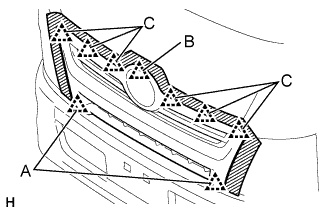
Partially attach the clips labeled A.
-
Attach the clip labeled B, and then attach the clips labeled C.
-
Fully attach the clips labeled A to install the radiator grille.
-
Install the screw.
-
-
INSTALL ROOF HEADLINING ASSEMBLY