INSTRUMENT PANEL SAFETY PAD INSTALLATION

-
INSTALL INSTRUMENT PANEL SUB-ASSEMBLY
-
Attach the 3 guides to install the instrument panel sub-assembly.
-
Install the 4 bolts <A> and 2 bolts <C> and 2 nuts <B>.
-
Attach each clamp.
-
Connect each connector.
-
-
INSTALL HEATER CONTROL AND ACCESSORY ASSEMBLY
-
Install the heater control and accessory assembly with the 3 screws.
-
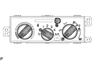
Set the heater control levers to the positions shown in the illustration.
Component Setting Mode Control Lever FACE Heater Control Lever MAX COOL Air Inlet Control Lever FRESH -
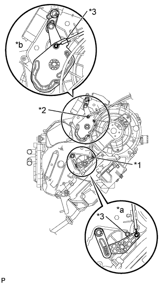
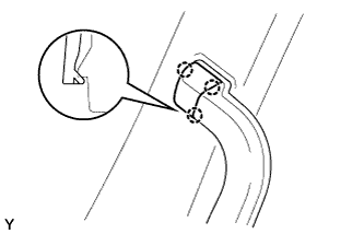
Text in Illustration *1 No. 1 heater control cable sub-assembly *2 Airmix damper control cable sub-assembly *3 Boss *a MAX COOL position *b FACE position Connect the No. 1 heater control cable sub-assembly.
-
Install the tip of the inner cable to the control lever at the MAX COOL position.
-
While pulling the outer cable so that it firmly contacts the boss, install the outer cable to the cable clip.
Note
Operate the temperature control lever and confirm that the lever stops properly at both the MAX COOL and MAX HOT positions, and that the lever does not move back out of position by itself.
-
-
Connect the airmix damper control cable sub-assembly
-
Install the tip of the inner cable to the control lever at the FACE position.
-
While pulling the outer cable so that it firmly contacts the boss, install the outer cable to the cable clip.
Note
Operate the mode change control lever and confirm that the lever stops properly at both the FACE and DEF positions, and that the lever does not move back out of position by itself.
-
-
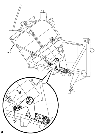
Text in Illustration *1 Air inlet damper control cable sub-assembly *2 Boss *a FRESH position Connect the air inlet damper control cable sub-assembly.
-
Install the tip of the inner cable to the control lever at the FRESH position.
-
While pulling the outer cable so that it firmly contacts the boss, install the outer cable to the cable clip.
Note
Operate the air intake mode control lever and confirm that the lever stops properly at both the FRESH and RECIRC positions, and that the lever does not move back out of position by itself.
-
-
-
INSTALL INSTRUMENT PANEL JUNCTION BLOCK ASSEMBLY
-
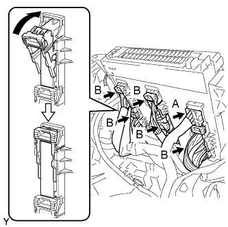
Connect the 5 B connectors to the back of the instrument panel junction block assembly as shown in the illustration.
Note
Make sure the connectors are securely connected.
-
Connect the A connector.
-
Install the instrument panel junction block assembly with the 2 bolts.
- Torque:
- 6.0 N*m { 61 kgf*cm, 53 in.*lbf }
-
-
INSTALL STEREO OPENING COVER
-
Install the stereo opening cover with the 4 bolts.
- Torque:
- 5.0 N*m { 51 kgf*cm, 44 in.*lbf }
-
-
INSTALL STEREO OPENING COVER
-
Install the stereo opening cover with the 3 screws <H>.
-
-
CONNECT FRONT WASHER TANK CAP
-
Connect the front washer tank cap to the instrument panel sub-assembly.
-
-
INSTALL WINDSHIELD WASHER JAR CAP
-
Install the front washer tank cap.
-
-
INSTALL OIL RESERVOIR TANK COVER LH
-
Engage the 4 claws and 3 guides to install the oil reservoir tank cover LH.
-
-
INSTALL FRONT NO. 1 SPEAKER ASSEMBLY
Tech Tips
Use the same procedure for the other front No. 1 speaker assembly.
-
Connect the connector.
-
Install the front No. 1 speaker assembly with the 3 screws.
-
-
INSTALL NO. 1 INSTRUMENT PANEL SPEAKER PANEL SUB-ASSEMBLY
-
Attach the 2 guides and 2 claws to install the No. 1 instrument panel speaker panel sub-assembly.
-
-
INSTALL NO. 2 INSTRUMENT PANEL SPEAKER PANEL SUB-ASSEMBLY
Tech Tips
Use the same procedure described for the No. 1 instrument panel speaker panel sub-assembly.
-
INSTALL NO. 2 INSTRUMENT PANEL BOX
-
Attach the 3 clips and 2 guides to install the No. 2 instrument panel box.
-
Install the bolt <G>.
-
-
INSTALL NO. 1 INSTRUMENT PANEL BOX
-
Attach the 2 wire harness clamps.
-
Attach the 4 clips, claw and guide to install the No. 1 instrument panel box.
-
Install the bolt <G>.
-
-
INSTALL LOWER INSTRUMENT COVER SUB-ASSEMBLY
-
Attach the 4 clips and guide to install the lower instrument cover sub-assembly.
-
Install the 2 bolts <D>.
-
Install the clip.
-
-
INSTALL FUSE BOX OPENING COVER
-
Attach the 2 guides and 2 claws to install the fuse box opening cover.
-
-
INSTALL LOWER INSTRUMENT PANEL
-
Attach the 8 clips to install the lower instrument panel.
-
Install the 3 bolts <D>.
-
Install the clip.
-
-
INSTALL LOWER INSTRUMENT COVER
-
Install the 4 clips to install the lower instrument cover.
-
-
INSTALL INSTRUMENT PANEL BOX HOLDER
-
Install the instrument panel box holder with the 2 screws <E>.
-
-
INSTALL INSTRUMENT PANEL BOX
-
Attach the 6 clips to instrument panel box.
-
-
INSTALL COMBINATION METER ASSEMBLY
-
Connect each connector.
-
Install the combination meter assembly with the 4 screws.
-
-
INSTALL NO. 1 INSTRUMENT CLUSTER FINISH PANEL
-
Attach the 6 clips to install the No. 1 instrument cluster finish panel.
-
-
INSTALL CENTER INSTRUMENT CLUSTER FINISH PANEL SUB-ASSEMBLY
-
Connect each connector.
-
Attach the 13 clips to install the center instrument cluster finish panel sub-assembly.
-
-
INSTALL UPPER STEERING COLUMN COVER
-
Engage the 3 claws and install the steering column cover plate.
-
Install the upper steering column cover onto the steering column.
-
-
INSTALL LOWER STEERING COLUMN COVER
-
Engage the 4 claws and install the lower steering column cover.
-
Install the 5 screws.
-
-
INSTALL LOWER INSTRUMENT PANEL FINISH PANEL SUB-ASSEMBLY RH
-
Connect each connector.
-
Attach the 5 clips to install the lower instrument panel finish panel sub-assembly.
-
-
INSTALL LOWER INSTRUMENT PANEL FINISH PANEL SUB-ASSEMBLY LH
-
Connect each connector.
-
Attach the 3 clips to install the lower instrument panel finish panel sub-assembly LH.
-
Install the 2 clips.
-
-
INSTALL FRONT PILLAR GARNISH RH
-
Attach the 2 clips to install the front pillar garnish RH.
-
-
INSTALL FRONT PILLAR GARNISH LH
Tech Tips
Use the same procedure described for the RH side.
-
INSTALL NO. 2 ASSIST GRIP ASSEMBLY RH
-
Install the No. 2 assist grip assembly RH with the 2 bolts.
- Torque:
- 14 N*m { 138 kgf*cm, 10 ft.*lbf }
-
-
INSTALL NO. 2 ASSIST GRIP ASSEMBLY LH
Tech Tips
Use the same procedure described for the RH side.
-
INSTALL ASSIST GRIP PLUG
Tech Tips
Use the same procedure for the other assist grip plug.
-
Attach the 3 claws to install the assist grip plug.
-
-
CONNECT CABLE TO NEGATIVE BATTERY TERMINAL
Note
When disconnecting the cable some systems need to be initialized after the cable is reconnected Click here