METER / GAUGE SYSTEM Speed Signal Circuit
DESCRIPTION
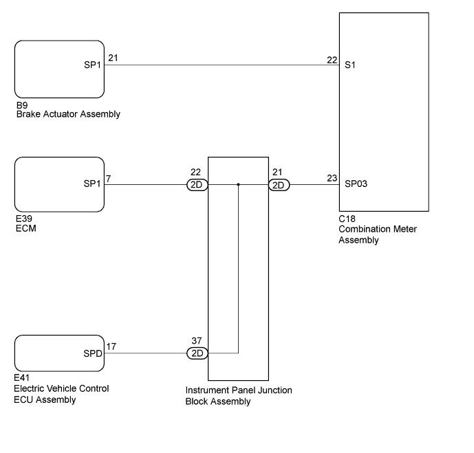
The combination meter assembly receives the vehicle speed signal from this circuit. The wheel speed sensors produce an output that varies according to the vehicle speed. The wheel speed sensor output is received by the brake actuator assembly, which uses this information to create the vehicle speed sensor signal. The vehicle speed sensor signal consists of pulses sent to the combination meter assembly from the brake actuator assembly. To create this signal, 24 V is output from S1, which is behind a resistor in the combination meter assembly. This voltage is sent to the brake actuator assembly. The pulse signal is created by switching the transistor in the brake actuator assembly on and off, making the voltage on the wire drop to 0 V. A similar system is used for the output of this signal from the combination meter assembly via terminal SPO2. A voltage of 9 to 28 V is applied to terminal SPO2 from each ECU or relay that is connected to this terminal. The transistor in the combination meter assembly is controlled by the signal from the brake actuator assembly. When this transistor is turned on, this transistor makes the voltage supplied by the various ECUs (via their respective internal resistors) drop to 0 V. Each ECU connected to terminal SPO2 of the combination meter assembly controls its respective system based on the pulse signal.
WIRING DIAGRAM
INSPECTION PROCEDURE
PROCEDURE
-
INSPECT COMBINATION METER ASSEMBLY (INPUT VOLTAGE)
-
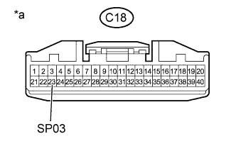
Text in Illustration *a Front view of wire harness connector
(to Combination Meter Assembly)
Disconnect the combination meter assembly connector.
-
Measure the voltage according to the value(s) in the table below.
Standard Voltage Tester Connection Switch Condition Specified Condition C18-23 (SP03) - Body ground Ignition switch ON 9 to 28 V Tech Tips
If any of the ECUs specified in the wiring diagram supplies power to the combination meter assembly, the combination meter assembly will output a waveform.
NG 
CHECK HARNESS AND CONNECTOR (COMBINATION METER ASSEMBLY - INSTRUMENT PANEL JUNCTION BLOCK ASSEMBLY) Click here
OK 
-
-
INSPECT COMBINATION METER ASSEMBLY (OUTPUT VOLTAGE)
-
Disconnect the brake actuator assembly connector.
-
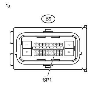
Text in Illustration *a Front view of wire harness connector
(to Brake Actuator Assembly)
Measure the resistance according to the value(s) in the table below.
Standard Resistance Tester Connection Switch Condition Specified Condition B9-21 (SP1) - Body ground Ignition switch ON 20 to 28 V
NG
OK
-
-
INSPECT BRAKE ACTUATOR ASSEMBLY (INPUT WAVEFORM)
-
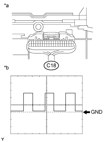
Text in Illustration *a Component with harness connected
(Combination Meter Assembly)
*b Waveform Check the input waveform.
-
Remove the combination meter assembly with the connector(s) still connected.
-
Connect an oscilloscope to terminal C18-22 (S1) and body ground.
-
Turn the ignition switch to ON.
-
Turn the wheel slowly.
-
Check the signal waveform according to the condition(s) in the table below.
Standard Item Condition Tool setting 5 V/DIV., 20 ms./DIV. Condition Driving at approximately 20 km/h (12 mph) OK The waveform is displayed as shown in the illustration. Tech Tips
As the vehicle speed increases, the cycle of the waveform narrows.
-
NG 
REPLACE BRAKE ACTUATOR ASSEMBLY Click here
OK 
REPLACE COMBINATION METER ASSEMBLY Click here
-
-
CHECK HARNESS AND CONNECTOR (COMBINATION METER ASSEMBLY - BRAKE ACTUATOR ASSEMBLY)
-
Disconnect the C18 combination meter assembly connector.
-
Disconnect the B9 brake actuator assembly connector.
-
Measure the resistance according to the value(s) in the table below.
Standard Resistance Tester Connection Condition Specified Condition C18-22 (S1) - B9-21 (SP1) Always Below 1 Ω C18-22 (S1) or B9-21 (SP1) - Body ground Always 10 kΩ or higher
NG
REPAIR OR REPLACE HARNESS OR CONNECTOR
OK
REPLACE COMBINATION METER ASSEMBLY Click here
-
-
CHECK HARNESS AND CONNECTOR (COMBINATION METER ASSEMBLY - INSTRUMENT PANEL JUNCTION BLOCK ASSEMBLY)
-
Disconnect the 2D instrument panel junction block assembly connector.
-
Disconnect the C18 combination meter assembly connector.
-
Measure the resistance according to the value(s) in the table below.
Standard Resistance Tester Connection Condition Specified Condition C18-23 (SP03) - 2D-21 Always Below 1 Ω C18-23 (SP03) or 2D-21 - Body ground Always 10 kΩ or higher
NG
REPAIR OR REPLACE HARNESS OR CONNECTOR
OK
-
-
INSPECT ECM
-
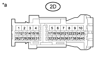
Text in Illustration *a Front view of wire harness connector
(to Instrument Panel Junction Block Assembly)
Disconnect the instrument panel junction block assembly connector.
-
Measure the voltage according to the value(s) in the table below.
Standard Voltage Tester Connection Switch Condition Specified Condition 2D-22 - Body ground Ignition switch ON 9 to 28 V
NG
CHECK HARNESS AND CONNECTOR (INSTRUMENT PANEL JUNCTION BLOCK ASSEMBLY - ECM) Click here
OK
-
-
INSPECT ELECTRIC VEHICLE CONTROL ECU ASSEMBLY
-
Text in Illustration *a Front view of wire harness connector
(to Instrument Panel Junction Block Assembly)
Disconnect the instrument panel junction block assembly connector.
-
Measure the voltage according to the value(s) in the table below.
Standard Voltage Tester Connection Switch Condition Specified Condition 2D-37 - Body ground Ignition switch ON 9 to 28 V
NG
CHECK HARNESS AND CONNECTOR (INSTRUMENT PANEL JUNCTION BLOCK ASSEMBLY - ELECTRIC VEHICLE CONTROL ECU ASSEMBLY) Click here
OK
REPLACE INSTRUMENT PANEL JUNCTION BLOCK ASSEMBLY
-
-
CHECK HARNESS AND CONNECTOR (INSTRUMENT PANEL JUNCTION BLOCK ASSEMBLY - ECM)
-
Disconnect the 2D instrument panel junction block assembly connector.
-
Disconnect the E39 ECM connector.
-
Measure the resistance according to the value(s) in the table below.
Standard Resistance Tester Connection Condition Specified Condition 2D-22 - E39-7 (SP1) Always Below 1 Ω 2D-22 or E39-7 (SP1) - Body ground Always 10 kΩ or higher
NG
REPAIR OR REPLACE HARNESS OR CONNECTOR
OK
REPLACE ECM Click here
-
-
CHECK HARNESS AND CONNECTOR (INSTRUMENT PANEL JUNCTION BLOCK ASSEMBLY - ELECTRIC VEHICLE CONTROL ECU ASSEMBLY)
-
Disconnect the 2D instrument panel junction block assembly connector.
-
Disconnect the E41 electric vehicle control ECU assembly connector.
-
Measure the resistance according to the value(s) in the table below.
Standard Resistance Tester Connection Condition Specified Condition 2D-37 - E41-17 (SPD) Always Below 1 Ω 2D-37 or E41-17 (SPD) - Body ground Always 10 kΩ or higher
NG
REPAIR OR REPLACE HARNESS OR CONNECTOR
OK
REPLACE ELECTRIC VEHICLE CONTROL ECU ASSEMBLY Click here
-