METER / GAUGE SYSTEM Fuel Receiver Gauge Malfunction
DESCRIPTION
-
The combination meter assembly controls the fuel receiver gauge in accordance with the resistance of the fuel sender gauge assembly, which varies depending on the amount of fuel remaining in the fuel tank.
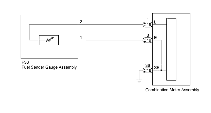
WIRING DIAGRAM
INSPECTION PROCEDURE
PROCEDURE
-
INSPECT FUEL SENDER GAUGE ASSEMBLY
-
Remove the fuel sender gauge assembly Click here.
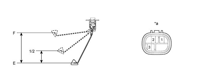
Text in Illustration *a Component without harness connected
(Fuel Sender Gauge Assembly)
- - -
Check that the float moves smoothly between F and E.
-
Measure the resistance according to the value(s) in the table below.
Standard Resistance Tester Connection Float Level Float Position (mm (in.)) Specified Condition 1 - 2 F 228.4 to 238.4 (8.992 to 9.386) 2.4 to 3.6 Ω 1/2 122.8 to 127.8 (4.835 to 5.031) 31 to 34 Ω E 0 (0) 107.5 to 112.5 Ω
NG 
REPLACE FUEL SENDER GAUGE ASSEMBLY Click here
OK 
-
-
CHECK HARNESS AND CONNECTOR (COMBINATION METER ASSEMBLY - FUEL SENDER GAUGE ASSEMBLY)
-
Disconnect the C18 and C19 combination meter assembly connectors.
-
Disconnect the F30 fuel sender gauge assembly connector.
-
Measure the resistance according to the value(s) in the table below.
Standard Resistance Tester Connection Condition Specified Condition C19-1 (L) - F30-2 Always Below 1 Ω C19-1 (L) or F30-2 - Body ground Always 10 kΩ or higher C19-3 (E) - F30-1 Always Below 1 Ω C19-3 (E) or F30-1 - Body ground Always 10 kΩ or higher C18-36 (SE) - Body ground Always Below 1 Ω
NG
REPAIR OR REPLACE HARNESS OR CONNECTOR
OK 
REPLACE COMBINATION METER ASSEMBLY Click here
-