METER / GAUGE SYSTEM Speedometer Malfunction
DESCRIPTION
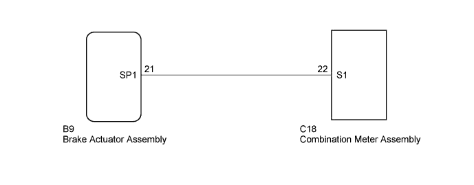
The combination meter assembly controls the speedometer in accordance with vehicle speed signals from the brake actuator assembly.
WIRING DIAGRAM
INSPECTION PROCEDURE
PROCEDURE
-
READ VALUE USING INTELLIGENT TESTER (VEHICLE SPEED)
-
Connect the intelligent tester to the DLC3.
-
Turn the ignition switch to ON.
-
Turn the intelligent tester on.
-
Enter the following menus: Chassis / ABS/VSC/TRC / Data List.
-
According to the display on the tester, read the Data List.
ABS/VSC/TRC Tester Display Measurement Item/Range Normal Condition Diagnostic Note Vehicle Speed Maximum wheel speed sensor reading/
Min.: 0 km/h (0 mph)
Max.: 326 km/h (202 mph)
Vehicle stopped: 0 km/h (0 mph) When driving at constant speed: No large fluctuations OK Vehicle speed displayed on the tester is approximately the same as the actual vehicle speed.
NG 
GO TO ANTI-LOCK BRAKE SYSTEM Click here
OK 
-
-
INSPECT COMBINATION METER ASSEMBLY (OUTPUT VOLTAGE)
-
Disconnect the brake actuator assembly connector.
-
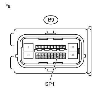
Text in Illustration *a Front view of wire harness connector
(to Brake Actuator Assembly)
Measure the resistance according to the value(s) in the table below.
Standard Resistance Tester Connection Switch Condition Specified Condition B9-21 (SP1) - Body ground Ignition switch ON 20 to 28 V
NG 
CHECK HARNESS AND CONNECTOR (COMBINATION METER ASSEMBLY - BRAKE ACTUATOR ASSEMBLY) Click here
OK 
REPLACE COMBINATION METER ASSEMBLY Click here
-
-
INSPECT BRAKE ACTUATOR ASSEMBLY (INPUT WAVEFORM)
-
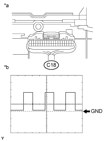
Text in Illustration *a Component with harness connected
(Combination Meter Assembly)
*b Waveform Check the input waveform.
-
Remove the combination meter assembly with the connector(s) still connected.
-
Connect an oscilloscope to terminal C18-22 (S1) and body ground.
-
Turn the ignition switch to ON.
-
Turn the wheel slowly.
-
Check the signal waveform according to the condition(s) in the table below.
Standard Item Condition Tool setting 5 V/DIV., 20 ms./DIV. Condition Driving at approximately 20 km/h (12 mph) OK The waveform is displayed as shown in the illustration. Tech Tips
As the vehicle speed increases, the cycle of the waveform narrows.
-
NG
REPLACE BRAKE ACTUATOR ASSEMBLY Click here
OK
REPLACE COMBINATION METER ASSEMBLY Click here
-
-
CHECK HARNESS AND CONNECTOR (COMBINATION METER ASSEMBLY - BRAKE ACTUATOR ASSEMBLY)
-
Disconnect the C18 combination meter assembly connector.
-
Disconnect the B9 brake actuator assembly connector.
-
Measure the resistance according to the value(s) in the table below.
Standard Resistance Tester Connection Condition Specified Condition C18-22 (S1) - B9-21 (SP1) Always Below 1 Ω C18-22 (S1) or B9-21 (SP1) - Body ground Always 10 kΩ or higher
NG
REPAIR OR REPLACE HARNESS OR CONNECTOR
OK
REPLACE COMBINATION METER ASSEMBLY Click here
-