METER / GAUGE SYSTEM Tachometer Malfunction
DESCRIPTION
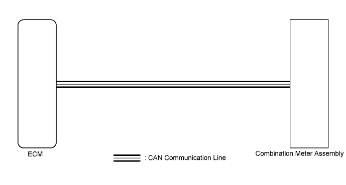
In this circuit, the meter CPU receives engine speed signals from the ECM using the CAN communication system. The meter CPU displays the engine speed calculated based on the data received from the ECM.
WIRING DIAGRAM
INSPECTION PROCEDURE
PROCEDURE
-
CHECK CAN COMMUNICATION SYSTEM
-
Check if a CAN communication DTC is output Click here.
Result Result Proceed to CAN communication DTC is not output A CAN communication DTC is output B
B 
GO TO CAN COMMUNICATION SYSTEM Click here
A 
-
-
CHECK ENGINE CONTROL SYSTEM
-
Check if a engine control DTC is output Click here.
Result Result Proceed to Engine control DTC is not output A Engine control DTC is output B
B
GO TO ECD SYSTEM Click here
A 
REPLACE COMBINATION METER ASSEMBLY Click here
-