METER / GAUGE SYSTEM ON-VEHICLE INSPECTION

-
INSPECT SPEEDOMETER
-
Using a speedometer tester (calibrated chassis dynamometer), check the speedometer for allowable indication error and check the operation of the odometer.
Reference: Chassis Dynamometer Indication Allowable Range 20 km/h 20.5 to 24.6 km/h 40 km/h 40.9 to 45.3 km/h 60 km/h 61.3 to 66.0 km/h 80 km/h 81.7 to 86.7 km/h 100 km/h 102.1 to 107.5 km/h 120 km/h 122.5 to 128.2 km/h 140 km/h 142.9 to 148.9 km/h Note
Tire wear, over inflation, or under inflation will cause errors.
-
Check the deviation from the acceptable range of the speedometer indication.
Reference Less than 0.5 km/h (0.3 mph)
-
-
INSPECT OUTPUT SIGNAL OF VEHICLE SPEED
-
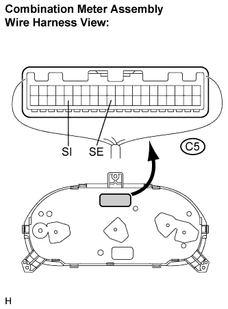
While driving the vehicle at the speed of 10 km/h (6.2 mph), check the voltage between terminals C5-36 (SI) and C5-31 (SE) of the combination meter assembly.
OK The waveform will fluctuate 8 times every rotation of the rotor shaft. The fluctuations will be between 0 V at the bottom of the waveform and 20 to 28 V at the top of the waveform. Note
Check it with the ignition switch in the ON position and the connector connected.
-
-
INSPECT TACHOMETER
-
Connect a tune-up test tachometer, and start the engine.
Note
-
Reversing the connection of the tachometer will damage the transistors and diodes inside.
-
When removing or installing the tachometer, be careful not to drop or subject it to heavy shocks.
-
-
Compare the test results with the tachometer indications.
Reference: DC 27.0 V at 25°C (77°F) Tune-up Test Tachometer Indication (rpm) Allowable Range (rpm)
Data in ( ) are for reference
700 630 to 770 1,000 (900 to 1,100) 2,000 (1,850 to 2,150) 3,000 2,800 to 3,200
-
-
INSPECT FUEL RECEIVER GAUGE
-
Disconnect the connector from the sender gauge.
-
Turn the ignition switch to the ON position, then check the position of the receiver gauge needle.
OK The gauge needle indicates EMPTY. -
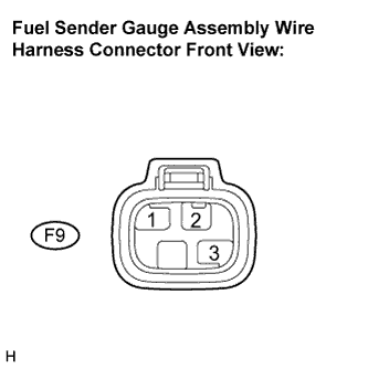
Connect terminals 1 and 2 on the wire harness side connector and turn the ignition switch to the ON position, then check the position of the receiver gauge needle.
OK The gauge needle indicates FULL. Tech Tips
If the result is not as specified, go to the problem symptoms table Click here.
-
-
INSPECT FUEL LEVEL WARNING LIGHT
-
Disconnect the connector from the sender gauge.
-
Turn the ignition switch to the ON position, check the fuel receiver gauge needle and fuel level warning light.
OK The gauge needle indicates EMPTY and fuel level warning light comes on. Tech Tips
If the result is not as specified, go to the problem symptoms table Click here
-
-
INSPECT ENGINE COOLANT TEMPERATURE RECEIVER GAUGE
-
Disconnect the connector from the water temperature sensor.
-
Turn the ignition switch to the ON position, check the position of the engine coolant temperature receiver gauge needle.
OK The gauge needle indicates COOL. -
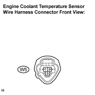
Ground terminal 1 on the wire harness side, then check the position of the engine coolant temperature receiver gauge needle.
OK The gauge needle indicates HOT. Tech Tips
If the result is not as specified, go to the problem symptoms table Click here.
-
-
INSPECT LOW OIL PRESSURE WARNING LIGHT
-
Disconnect the connector from the low oil pressure switch.
-
Turn the ignition switch to the ON position.
-
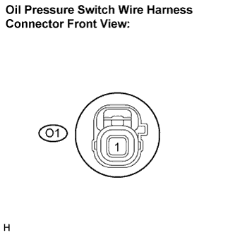
Connect the terminal on the wire harness side connector and ground, then check the low oil pressure warning light.
OK The low oil pressure warning light comes on. Tech Tips
If the result is not as specified, go to the problem symptoms table Click here.
-
-
INSPECT BRAKE WARNING LIGHT
-
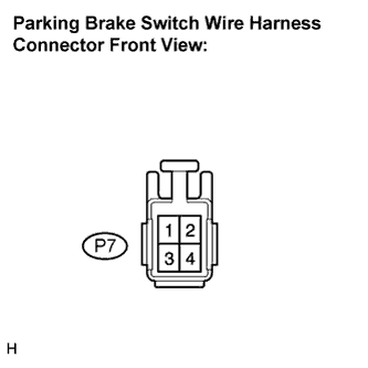
Disconnect the connector from the parking brake switch and ground terminal 2 on the wire harness side connector.
-
Turn the ignition switch to the ON position and check the warning light.
OK The brake warning light comes on. Tech Tips
If the result is not as specified, go to the problem symptoms table Click here.
-
-
INSPECT BRAKE FLUID LEVEL WARNING SWITCH
-
Remove the reservoir tank cap and strainer.
-
Disconnect the connector.
-

Measure the resistance between the terminals.
Float up (switch off) 10 kΩ or higher -
Use a syphon, etc. to take fluid out of the reservoir.
-
Measure the resistance between the terminals.
Float down (switch on) Below 1 Ω -
Pour the fluid back into the reservoir.
Tech Tips
If the result is not as specified, replace the brake master cylinder reservoir.
-
-
INSPECT FUEL SEDIMENTER WARNING LIGHT
-
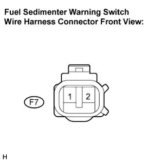
Disconnect the connector from the fuel sedimenter warning switch and ground terminal 1 on the wire harness side connector.
-
Turn the ignition switch to the ON position and check the warning light.
OK The fuel sedimenter warning light comes on. Tech Tips
If the result is not as specified, go to the problem symptoms table Click here.
-
-
INSPECT DPF WARNING LIGHT
-
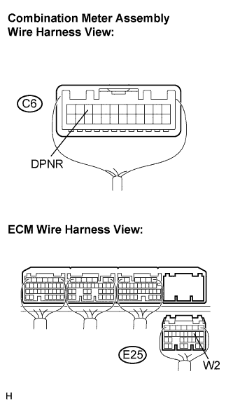
Disconnect the C6 and E25 connectors.
-
Measure the resistance according to the value(s) in the table below.
Standard resistance Tester Connection Condition Specified Condition C6-10 (DPNR) - E25-10 (W2) Always Below 1 Ω C6-10 (DPNR) - Body ground Always 10 kΩ or higher Tech Tips
If the result is not as specified, repair or replace the harness or connector.
-
Remove the combination meter assembly.
-
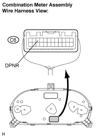
Reconnect the C6 connector.
-
Measure the voltage according to the value(s) in the table below.
Standard voltage Tester Connection Condition Specified Condition C6-10 (DPNR) - Body ground Turn the ignition switch to the ON position, DPF switch is pressed 20 to 28 V
(DPF warning light comes on)
Tech Tips
If the result is not as specified, replace the combination meter assembly (See Pub. No. RM1008E).
-