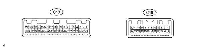
METER / GAUGE SYSTEM TERMINALS OF ECU

-
COMBINATION METER ASSEMBLY
-
Disconnect the C18 combination meter assembly connector.
-
Measure the voltage and resistance of the wire harness side connector.
Terminal No. (Symbol) Wiring Color Terminal Description Condition Specified Condition C18-36 (SE) - Body ground BR - Body ground Ground Always Below 1 Ω C18-39 (IG+) - Body ground R - Body ground Ignition switch signal Ignition switch off → ON Below 2 V → 20 to 28 V C18-40 (B) - Body ground B - Body ground Battery Always 20 to 28 V If the result is not as specified, there may be a malfunction in the wire harness.
-
Connect the C18 combination meter assembly connector.
-
Measure the voltage and resistance of the wire harness side connector.
Terminal No. (Symbol) Wiring Color Terminal Description Condition Specified Condition C18-2 (ILL+) - Body ground G - Body ground Taillight signal Light control switch OFF → ON Below 2 V → 20 to 28 V C18-6 (B) - Body ground P - Body ground Turn signal RH signal Ignition switch ON
Turn signal RH indicator light OFF → ON → OFF
Below 2 V → 20 to 28 V → Below 2 V C18-8 (+) - Body ground Y - Body ground HEAD light signal Light control switch OFF → ON Below 2 V → 20 to 28 V C18-10 (+) - Body ground W - Body ground Rear fog light signal Light control switch ON
Rear fog light switch OFF → ON
Below 2 V → 20 to 28 V C18-11 (FOG) - Body ground BR - Body ground Front fog light signal Light control switch ON
Front fog light switch OFF → ON
Below 2 V → 20 to 28 V C18-12 (MSTI) - Body ground G - Body ground VCS ECU warning light signal VCS ECU warning light OFF → ON 20 to 28 V → Below 2 V C18-13 (PTO+)*1 - Body ground R - Body ground PTO indicator light signal PTO indicator light OFF → ON Below 2 V → 20 to 28 V C18-14 (PTOE)*1 - Body ground GR - Body ground PTO indicator light signal PTO indicator light OFF → ON Below 2 V → 20 to 28 V C18-16 (PTO-)*1 - Body ground W-B - Body ground PTO indicator light signal Always Below 2 V C18-18 (GLW-) - Body ground R - Body ground GLOW indicator light signal GLOW indicator light ON → OFF Below 2 V → 20 to 28 V C18-22 (S1)- Body ground B - Body ground Vehicle speed signal (Input) Driving at approximately 20 km/h (12 mph) Pulse generation
(See waveform 1)
C18-23 (SP03) - Body ground L - Body ground Vehicle speed signal (Output) Driving at approximately 20 km/h (12 mph) Pulse generation
(See waveform 1)
C18-25 (CHG-) - Body ground W - Body ground Charge warning light signal Ignition switch ON → off 20 to 28 V → Below 2 V C18-31 (ES) - Body ground R - Body ground ES start warning light signal ES start warning light ON → OFF Below 2 V → 20 to 28 V C18-34 (CHK) - Body ground GR - Body ground MIL signal MIL signal ON → OFF Below 2 V → 20 to 28 V C19-1 (L) - Body ground R - Body ground Fuel level signal Ignition switch ON 20 to 28 V C19-2 (DCTY) - Body ground P - Body ground Driver side door open Driver side door open → closed Below 2 V → 20 to 28 V C19-3 (E) - Body ground W - Body ground Fuel level signal Ignition switch ON 20 to 28 V C19-4 (DPNR) - Body ground V - Body ground DPF warning light signal DPF warning light ON → OFF Below 2 V → 20 to 28 V C19-6 (SW) - Body ground Y- Body ground SRS warning light signal SRS warning light ON → OFF Below 2 V → 20 to 28 V C19-10 (SW) - Body ground G - Body ground Brake fluid level warning light signal Brake fluid level warning light ON → OFF Below 2 V → 20 to 28 V C19-13 (CANL) - Body ground G - Body ground CAN communication signal Ignition switch off 200 Ω or higher C19-14 (CANH) - Body ground L - Body ground CAN communication signal Ignition switch off 200 Ω or higher C19-16 (TILT) - Body ground W - Body ground Cab tilt warning light signal Cab tilt warning light ON → OFF Below 2 V → 20 to 28 V C19-18 (PKB) - Body ground R - Body ground Brake warning light signal Brake warning light ON → OFF Below 2 V → 20 to 28 V C19-19 (B) - Body ground G - Body ground Driver side seat belt warning light signal Driver side seat belt warning light ON → OFF Below 2 V → 20 to 28 V C19-20 (VCM) - Body ground V - Body ground Vacuum switch signal Brake warning light ON → OFF Below 2 V → 20 to 28 V C19-21 (KSW) - Body ground SB - Body ground Key switch condition signal Key inserted → removed Below 2 V → 20 to 28 V C19-22 (B) - Body ground LG - Body ground Turn signal LH signal Ignition switch ON
Turn signal LH indicator light OFF → ON → OFF
Below 2 V → 20 to 28 V → Below 2 V C19-23 (BLP) - Body ground R - Body ground Reverse warning buzzer signal Reverse warning buzzer ON → OFF Below 2 V → 20 to 28 V
-
*1: for Power Take-off Electric Type
-
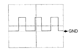
Waveform 1: Using an oscilloscope
Terminal Connections C18-22 (S1) - Body ground
C18-23 (SP03) - Body ground
Tool Setting 5 V/DIV., 20 ms/DIV. Condition Driving at approximately 20 km/h (12 mph) Tech Tips
As the vehicle speed increases, the cycle of the signal waveform narrows.
-
-