METER / GAUGE SYSTEM TERMINALS OF ECU

-
COMBINATION METER ASSEMBLY
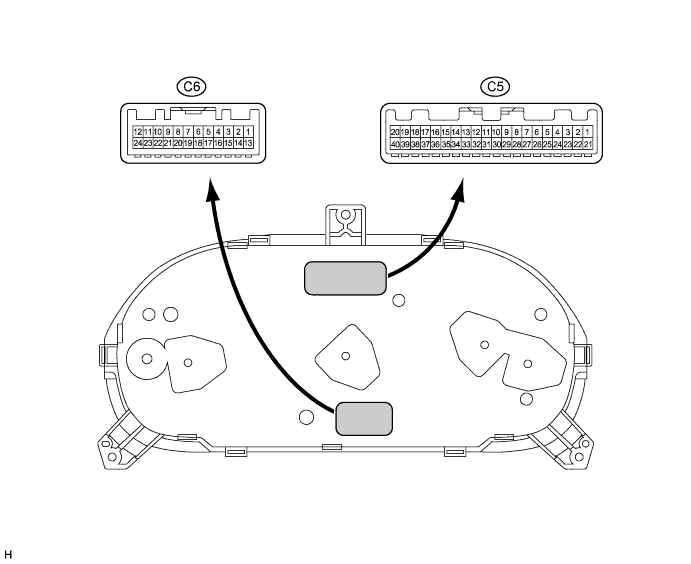
Terminal No.
(Symbols)
Wiring Color Terminal Description Condition Specified Condition C5-2 (+) - Body ground LG - Body ground Beam indicator light signal Ignition switch ON, beam indicator light OFF Below 2 V Ignition switch ON, beam indicator light ON 20 to 28 V C5-4 (B) - Body ground L - Body ground Exhaust brake indicator light signal Ignition switch ON, exhaust brake indicator light OFF Below 2 V Ignition switch ON, exhaust brake indicator light ON 20 to 28 V C5-9 (+) - Body ground Y - Body ground Rear fog indicator light signal Ignition switch ON, rear fog indicator light OFF Below 2 V Ignition switch ON, rear fog indicator light ON 20 to 28 V C5-14 (S) - Body ground P-L - Body ground Engine oil pressure warning light signal Ignition switch ON, oil pressure warning light OFF 20 to 28 V Ignition switch ON, oil pressure warning light ON Below 2 V C5-16 (PKB) - Body ground B-Y - Body ground Brake warning light signal (Brake fluid level warning switch) Ignition switch ON, brake warning light OFF 20 to 28 V Ignition switch ON, brake warning light ON Below 2 V C5-17 (B) - Body ground G-Y - Body ground Turn signal flasher Ignition switch ON, turn signal RH indicator light OFF Below 2 V Ignition switch ON, turn signal RH indicator light ON 20 to 28 V C5-19 (PKBI) - Body ground P-B - Body ground Parking brake warning light signal and parking brake switch signal Ignition switch ON, parking brake warning light OFF and parking brake switch OFF Below 2 V Ignition switch ON, parking brake warning light ON and parking brake switch ON 20 to 28 V C5-24 (B) - Body ground G-B - Body ground Turn signal flasher Ignition switch ON, turn signal LH indicator light OFF Below 2 V Ignition switch ON, turn signal LH indicator light ON 20 to 28 V C5-25 (EI) - Body ground W-B - Body ground Ground (Signal ground) Always Below 2 V C5-26 (L) - Body ground G-W - Body ground Fuel level signal Ignition switch ON, fuel level low 15 to 21 V Ignition switch ON, fuel level full 20 to 28 V C5-27 (B) - Body ground L-Y - Body ground Battery Always 20 to 28 V C5-28 (IG+) - Body ground R-L - Body ground Ignition switch signal Ignition switch OFF Below 2 V Ignition switch ON 20 to 28 V C5-29 (ILL+) - Body ground G - Body ground Illumination signal Ignition switch ON, light control switch OFF Below 2 V Ignition switch ON, light control switch TAIL/HEAD position 20 to 28 V C5-30 (ILL-) - Body ground W-B - Body ground Ground (Illumination ground) Always Below 2 V C5-31 (SE) - Body ground BR - Body ground Ground (Signal ground) Always Below 2 V C5-34 (HI) - Body ground L - Body ground Engine coolant temperature signal Ignition switch ON, engine coolant temperature low 2 to 3 V Ignition switch ON, engine coolant temperature high 3.5 to 4 V C5-35 (S) - Body ground P - Body ground Tachometer signal Ignition switch ON, engine idle speed Pulse generation
(See waveform 1)
C5-36 (SI) - Body ground B - Body ground Speed signal (Input) Ignition switch ON, wheel turned slowly Pulse generation
(See waveform 2)
C5-40 (ESC) - Body ground R-Y - Body ground ABS warning light signal Ignition switch ON, ABS warning light OFF Below 2 V Ignition switch ON, ABS warning light ON 20 to 28 V C6-7 (CHG-) - Body ground V - Body ground Charge warning light signal Ignition switch OFF Below 2 V Ignition switch ON 20 to 28 V C6-8 (CHG+) - Body ground GR - Body ground Charge warning light signal Ignition switch ON, charge warning light OFF 20 to 28 V Ignition switch ON, charge warning light comes ON Below 2 V C6-10 (DPNR) - Body ground B - Body ground DPF warning light signal Ignition switch ON, DPF warning light OFF 20 to 28 V Ignition switch ON, DPF warning light ON Below 2 V C6-12 (EGW) - Body ground R - Body ground Sedimenter warning light signal Ignition switch ON, sedimenter warning light OFF 20 to 28 V Ignition switch ON, sedimenter warning light ON Below 2 V C6-23 (WRN) - Body ground Y-R - Body ground Check engine warning light signal Ignition switch ON, check engine warning light OFF 20 to 28 V Ignition switch ON, check engine warning light ON Below 2 V
-
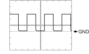
Waveform 1 (Reference): Using an oscilloscope:
OK: Item Condition Tool setting 10 V/DIV., 10 ms./DIV. Vehicle condition Engine idle speed -
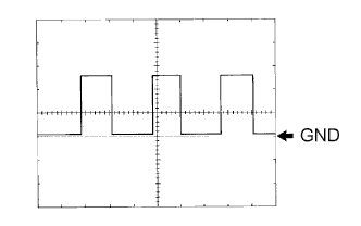
Waveform 2 (Reference): Using an oscilloscope:
OK: Item Condition Tool setting 10 V/DIV., 20 ms./DIV. Vehicle condition Driving at approx. 20 km/h (12 mph) Tech Tips
As vehicle speed increases, the cycle of the signal waveform narrows.
-
-
COMBINATION METER ASSEMBLY INNER CIRCUIT
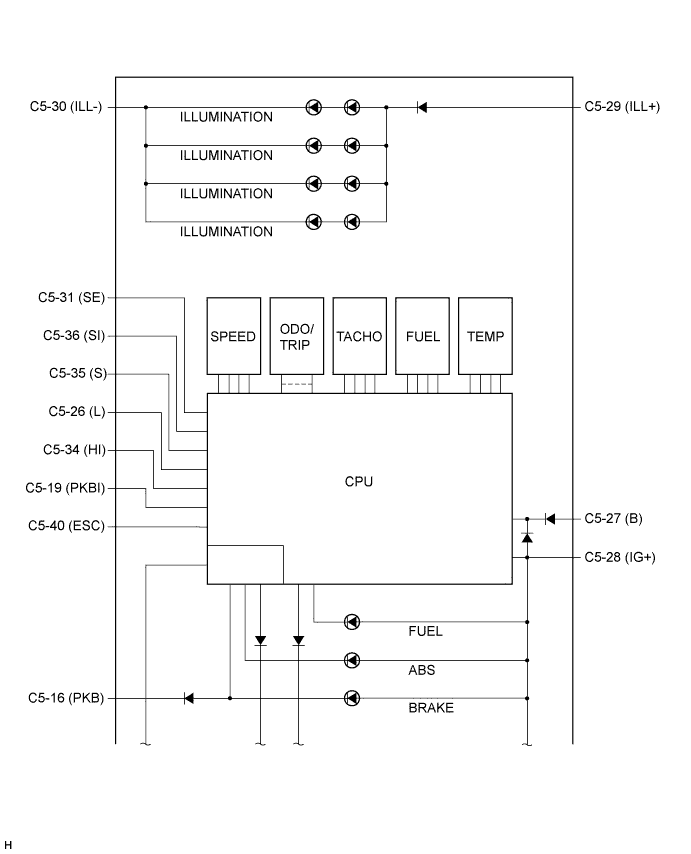
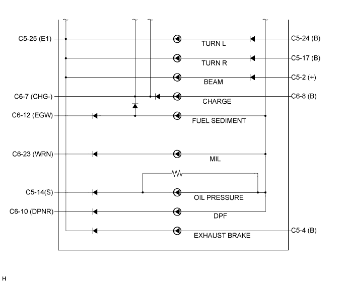
Terminal No. (Symbols) Wire Harness Side C5 1 - 2 (+) Light Control Switch 3 - 4 (B) ECM 5 - 6 - 7 - 8 - 9 (S) Rear Fog Light Switch 10 - 11 - 12 - 13 - 14 (S) Engine Oil Pressure Switch 15 - 16 (PKB) Parking Brake Switch 17 Turn Signal Flasher (B) 18 - 19 (PKBI) Skid Control ECU 20 - 21 - 22 - 23 - 24 (B) Turn Signal Flasher 25 (E1) Ground 26 (L) Fuel Sender Gauge Assembly 27 (B) ECU+B Fuse 28 (IG+) GAUGE Fuse 29 (ILL+) TAIL Fuse 30 (ILL-) Ground (Illumination Ground) 31 (SE) Vehicle Speed Sensor 32 - 33 - 34 (HI) Engine Coolant Temperature Sensor 35 (TAC) ECM 36 (SI) Tachograph 37 - 38 - 39 - 40 (ESC) Skid Control ECU C6 1 - 2 - 3 - 4 - 5 - 6 - 7 (CHG-) Generator 8 (B) Generator 9 - 10 (DPNR) ECM 11 - 12 (EGW) Fuel Sedimenter Warning Switch 13 - 14 - 15 - 16 - 17 - 18 - 19 - 20 - 21 - 22 - 23 (WRN) ECM 24 -