DOOR CONTROL RELAY ON-VEHICLE INSPECTION

-
INSPECT NO. 1 INTEGRATION RELAY
-
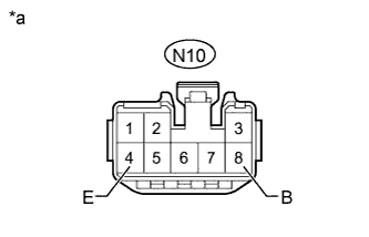
Text in Illustration *a Front view of wire harness connector
(to No. 1 Integration Relay)
Disconnect the N10 No. 1 integration relay connector.
-
Measure the voltage according to the value(s) in the table below.
Standard Voltage Tester Connection Condition Specified Condition N10-8 (B) - Body ground Always 20 to 28 V -
Measure the resistance according to the value(s) in the table below.
Standard Resistance Tester Connection Condition Specified Condition N10-4 (E) - Body ground Always Below 1 Ω -
Reconnect the N10 No.1 integration relay connector.
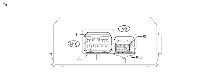
Text in Illustration *a Component with harness connected
(No. 1 Integration Relay)
- - -
Measure the voltage according to the value(s) in the table below.
Standard Voltage Tester Connection Condition Specified Condition N10-3 (L) - Body ground
-
Front door lock control knob (for driver side) unlocked
-
Driver side door key cylinder in unlock position
Below 1 V
-
Front door lock control knob (for Driver Side) locked
-
Driver side door key cylinder in lock position
20 to 28 V N10-7 (UL) - Body ground
-
Front door lock control knob (for driver side) locked
-
Driver side door key cylinder in lock position
Below 1 V
-
Front door lock control knob (for driver side) unlocked
-
Driver side door key cylinder in unlock position
20 to 28 V N9-2 (SL) - Body ground
-
Front door lock control knob (for driver side) locked
-
Driver side door key cylinder in lock position
Below 1 V
-
Front door lock control knob (for driver side) unlocked
-
Driver side door key cylinder in unlock position
4.5 to 5.5 V N9-3 (SUL) - Body ground
-
Front door lock control knob (for driver side) unlocked
-
Driver side door key cylinder in unlock position
Below 1 V
-
Front door lock control knob (for driver side) locked
-
Driver side door key cylinder in lock position
4.5 to 5.5 V If the result is not as specified, replace the No. 1 integration relay.
-
-