VOLTAGE CONVERTER SYSTEM DC / DC Converter Warning Light Circuit
DESCRIPTION
-
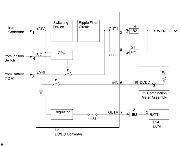
For models equipped with the N04C engine, 12 V power is used for engine control while the battery voltage is 24 V. Therefore, the DC/DC converter is used to supply 12 V power to the engine control system.
-
The DC/DC converter has two output circuits. One is the ECD system power source voltage circuit and the other is the ECM memory back-up voltage circuit. ECD system power source voltage is used as the main power source for the ECD system. When the ignition switch in ON position, the ECD system power source voltage circuit supplies 12 V power to the ECD system. ECM memory back-up voltage circuit always supplies 12 V.
ECD system power source voltage is output from terminal 2 or 8. ECM memory back-up voltage is output from terminal 7.
If either terminal 2 or 8 malfunctions, ECD system power source voltage can still be output from the other terminal.
-
The fail-safe function operates when the DC/DC converter has a malfunction.
During the operation (*2) described in the table below, the DC/DC converter will draw half of the voltage (12 V) from the midpoint between the two batteries connected in series, and supply the voltage to the ECD system.
The DC/DC converter illuminates the DC/DC CONV warning light in the combination meter to inform the driver that the function (*2) described in the table below is operating.
The vehicle can drive normally while the function (*2) described in the table below is operating, but the battery will be under extra load. Therefore, after the fail-safe function operates, be sure to check the battery voltage. If the battery voltage is below the specification, charge or replace the battery Click here for N04C-TW).
The DC/DC converter does not have the ability to set and store DTCs.
CAUTION:
Be sure to disconnect the battery terminal before connecting or disconnecting the DC/DC converter connectors. Failure to do so will cause sparks between the terminals, possibly resulting in damage to the connectors.
Note
-
Do not apply power from the DC/DC converter to systems other than the ECD system via bypassing a wire harness. The DC/DC converter output power is specifically designed for the ECD system. If DC/DC converter power is applied to other systems, the fail-safe function may operate due to overcurrent causing the DC/DC converter to stop functioning.
-
Keep the DC/DC converter away from water. The DC/DC converter structure is protected from raindrops, but the structure and connectors are not waterproof.
-
Do not cover the DC/DC converter area because the DC/DC converter generates heat while operating. Covering the DC/DC converter area will obstruct heat released from the DC/DC converter and may result in the converter overheating. If the overheat detection circuit built into the DC/DC converter operates, the DC/DC converter may stop power output if the fail-safe function operates.
Tech Tips
When the DC/DC converter operates normally, the following occurs:
-
When the ignition switch in ON position, the DC/DC CONV warning light will come on and go off after approximately 1 second.
-
When the ignition switch in ON position again within 30 seconds after turning the ignition switch in ACC position or off, the DC/DC CONV warning light will come on and go off after approximately 1 second. During this period, the DC/DC converter continues to output ECD system power source voltage.
-
The ECM memory back-up voltage circuit outputs 12 V no matter what position the ignition switch is in.
The following operations are fail-safe functions.
| Warning Light Condition | Condition | Fail-safe Operations | Fail-safe Deactivation Conditions |
|---|---|---|---|
| OFF | Ignition signal is not received |
|
Ignition switch signal is received |
| OFF | Ground fault (case ground) |
|
Ground circuit is completed |
| OFF | Voltage input to terminal No. 1 (+24 V) of the DC/DC converter is below 9 V |
|
Voltage input to terminal No. 1 (+24 V) of the DC/DC converter is 9 to 36 V |
| OFF | Voltage input to terminal No. 1 (+24 V) of the DC/DC converter is 9 to 18 V |
|
Voltage input to terminal No. 1 (+24 V) of the DC/DC converter is 18 to 36 V |
| OFF | Voltage input to terminal No. 1 (+24 V) of the DC/DC converter is 36 V or higher |
|
Voltage input to terminal No. 1 (+24 V) of the DC/DC converter is 18 to 36 V |
| ON | Voltage input to terminal No. 1 (+24 V) of the DC/DC converter is 18 to 36 V, and current output from terminals No. 2 (OUT1) and No. 8 (OUT2) of the DC/DC converter is 22 A or higher |
|
Current output from terminals No. 2 (OUT1) and No. 8 (OUT2) of the DC/DC converter is below 22 A
|
| ON | Current output from terminal No. 7 (OUTM) of the DC/DC converter is 5 A or higher |
|
DC/DC converter replacement (*1) |
| ON | ECD system power source voltage is 16 V or higher |
|
ECD system power source voltage is below 16 V
|
| ON | Voltage input to terminal No. 1 (+24 V) of the DC/DC converter is 18 to 36 V, and ECD system power source voltage is below 9 V |
|
DC/DC converter replacement (*3) |
| ON | Measured Temperature is too high |
|
Measured temperature is normal |
| ON | DC/DC converter internal voltage (5 V) is not normal |
|
DC/DC converter internal voltage (5 V) returns to normal
|
*1: Condition that the overcurrent protection circuit fuse (5 A) in the DC/DC converter is blown
*2: Condition that the DC/DC converter draws half of the voltage (12 V) from the midpoint between the two batteries connected in series, and supplies the voltage to the ECD system
*3: Internal malfunction of the DC/DC converter
WIRING DIAGRAM
-
System Diagram
-
Wiring Diagram
INSPECTION PROCEDURE
Before performing electrical work, disconnect the battery negative (-) terminal.
Note
If the battery negative (-) terminal is connected while connecting the DC/DC converter terminal, it may damage the voltage converter.
PROCEDURE
-
INSPECT DC/DC CONVERTER (BODY GROUND)
-
Measure the resistance according to the value(s) in the table below.
Standard resistance Tester Connection Condition Specified Condition DC/DC converter housing - Body ground Always Below 1 Ω
NG 
REPLACE DC/DC CONVERTER
OK 
-
-
SYSTEM CHECK
-
Ignition switch in ON position.
-
Check the warning light operation.
Result Result Proceed to The DC/DC converter warning light does not come on. A The DC/DC converter warning light remains on. B
B 
INSPECT DC/DC CONVERTER Click here
A
-
-
CHECK HARNESS AND CONNECTOR (POWER SOURCE)
-
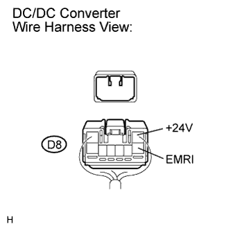
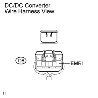
Disconnect the D8 connector.
-
Measure the voltage according to the value(s) in the table below.
Standard voltage Tester Connection Condition Specified Condition D8-1 (+24V) - Body ground Always 20 to 28 V D8-3 (EMRI) - Body ground Always 20 to 28 V
NG
REPAIR OR REPLACE HARNESS OR CONNECTOR
OK
-
-
INSPECT DC/DC CONVERTER (IGNITION SIGNAL)
-
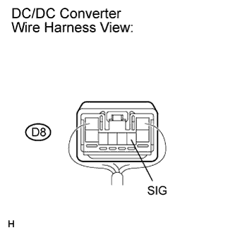
Reconnect the D8 connector.
-
Measure the voltage according to the value(s) in the table below.
Standard voltage Tester Connection Condition Specified Condition D8-4 (SIG) - Body ground Ignition switch in ON position Below 1 V
NG
REPAIR OR REPLACE HARNESS OR CONNECTOR
OK
-
-
INSPECT DC/DC CONVERTER
-
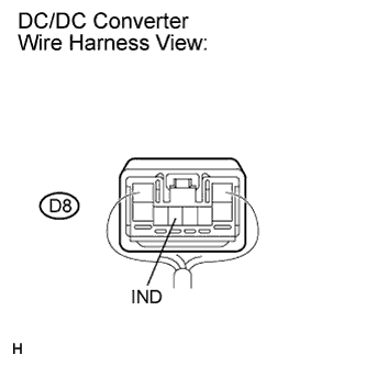
Disconnect the C5 combination meter connector.
-
Measure the resistance according to the value(s) in the table below.
Standard resistance Tester Connection Condition Specified Condition D8-6 (IND) - Body ground Always 10 kΩ or higher D8-6 (IND) - Body ground Ignition switch in ON position Below 1 Ω D8-6 (IND) - Body ground Ignition switch in ON position and wait for 1 second or more 10 kΩ or higher
NG
REPLACE DC/DC CONVERTER
OK 
GO TO METER / GAUGE SYSTEM
-
-
INSPECT DC/DC CONVERTER
-
Disconnect D8 connector.
-
Measure the voltage according to the value(s) in the table below.
Standard voltage Tester Connection Condition Specified Condition D8-3 (EMRI) - Body ground Always 11 to 14 V
NG
REPAIR OR REPLACE HARNESS OR CONNECTOR
OK
-
-
SYSTEM CHECK
-
Disconnect the ENG fuse.
-
Reconnect the C5 connector.
-
Ignition switch in ON position, then check the warning light operation.
Result Result Proceed to The DC/DC converter warning light remain on. (Normal operation) A The DC/DC converter warning light comes on for 1 second, then goes off. B
B
INSPECT DC/DC CONVERTER (OUTPUT VOLTAGE) Click here
A
GO TO ECD SYSTEM
-
-
INSPECT DC/DC CONVERTER (OUTPUT VOLTAGE)
-
Reconnect the D8 connector.
-
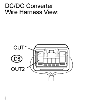
Measure the voltage according to the value(s) in the table below.
Standard voltage Tester Connection Condition Specified Condition D8-2 (OUT1) - Body ground Ignition switch in ON position 11 to 14 V D8-8 (OUT2) - Body ground Ignition switch in ON position 11 to 14 V
NG
REPLACE DC/DC CONVERTER
OK
-
-
INSPECT DC/DC CONVERTER (OUTPUT VOLTAGE FOR BACK-UP)
-
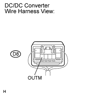
Measure the voltage according to the value(s) in the table below.
Standard voltage Tester Connection Condition Specified Condition D8-7 (OUTM) - Body ground Always 8 to 14 V
NG
REPAIR OR REPLACE HARNESS OR CONNECTOR
OK
REPLACE DC/DC CONVERTER
-