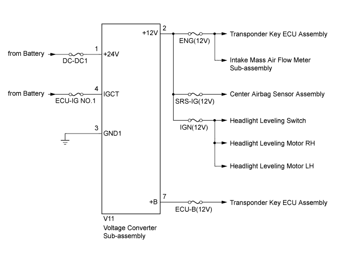
VOLTAGE CONVERTER SYSTEM DC / DC Converter Malfunction
WIRING DIAGRAM
INSPECTION PROCEDURE
Note
Inspect the fuses for circuits related to this system before performing the following inspection procedure.
PROCEDURE
-
CHECK HARNESS AND CONNECTOR (VOLTAGE CONVERTER SUB-ASSEMBLY - BODY GROUND)
-
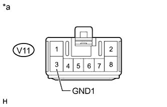
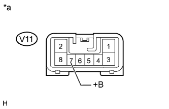
Text in Illustration *a Front view of wire harness connector
(to Voltage Converter Sub-assembly)
Disconnect the V11 voltage converter sub-assembly connector.
-
Measure the resistance according to the value(s) in the table below.
Standard Resistance Tester Connection Condition Specified Condition V11-3 (GND1) - Body ground Always Below 1 Ω
NG 
REPAIR OR REPLACE HARNESS OR CONNECTOR
OK 
-
-
CHECK HARNESS AND CONNECTOR (VOLTAGE CONVERTER SUB-ASSEMBLY - BATTERY)
-
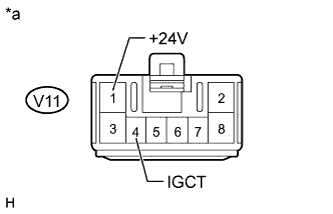
Text in Illustration *a Front view of wire harness connector
(to Voltage Converter Sub-assembly)
Disconnect the V11 voltage converter sub-assembly connector.
-
Measure the voltage according to the value(s) in the table below.
Standard Voltage Tester Connection Condition Specified Condition V11-1 (+24V) - Body ground Always 20 to 28 V V11-4 (IGCT) - Body ground Ignition switch ON 20 to 28 V Ignition switch off Below 1 V
NG
REPAIR OR REPLACE HARNESS OR CONNECTOR
OK
-
-
CHECK VOLTAGE CONVERTER SUB-ASSEMBLY (OUTPUT VOLTAGE)
-
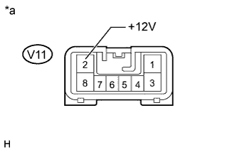
Text in Illustration *a Component with harness connected
(Voltage Converter Sub-assembly)
Disconnect the ENG(12V), SRS-IG(12V) and IGN(12V) fuses from driver side junction block assembly.
-
Measure the voltage according to the value(s) in the table below.
Standard Voltage Tester Connection Condition Specified Condition V11-2 (+12V) - Body ground Always 11 to 14 V (When 18 to 32 V is applied to terminal 1)
NG
REPLACE VOLTAGE CONVERTER SUB-ASSEMBLY Click here
OK
-
-
CHECK VOLTAGE CONVERTER SUB-ASSEMBLY (OUTPUT VOLTAGE FOR BACK-UP)
-
Text in Illustration *a Component with harness connected
(Voltage Converter Sub-assembly)
Disconnect the ECU-B(12V) fuse from driver side junction block assembly.
-
Measure the voltage according to the value(s) in the table below.
Standard Voltage Tester Connection Condition Specified Condition V11-7 (+B) - Body ground Always 8 to 14 V (When 18 to 32 V is applied to terminal 1)
NG
REPLACE VOLTAGE CONVERTER SUB-ASSEMBLY Click here
OK 
REPAIR OR REPLACE HARNESS OR CONNECTOR
-