HAZARD WARNING SWITCH INSPECTION

-
INSPECT HAZARD WARNING SIGNAL SWITCH ASSEMBLY
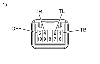
Text in Illustration *a Component without harness connected
(Hazard Warning Signal Switch Assembly)
-
Measure the resistance according to the value(s) in the table below.
Standard Resistance Tester Connection Switch Condition Specified Condition 1 (TB) - 5 (OFF) Hazard warning signal switch off Below 1 Ω 1 (TB) - 2 (TL) Hazard warning signal switch on Below 1 Ω 1 (TB) - 4 (TR) Below 1 Ω If the result is not as specified, replace the hazard warning signal switch assembly.
-
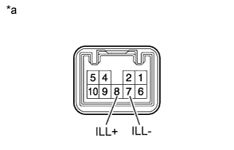
Text in Illustration *a Component without harness connected
(Hazard Warning Signal Switch Assembly)
Apply battery voltage to the connector and check the illumination condition.
OK Measurement Condition Specified Condition Battery positive (+) → Terminal 8 (ILL+)
Battery negative (-) → Terminal 7 (ILL-)
Illuminates If the result is not as specified, replace the hazard warning signal switch assembly.
-