WIPER ECU ON-VEHICLE INSPECTION

-
INSPECT NO. 1 INTEGRATION RELAY
-
Measure the voltage according to the value(s) in the table below.
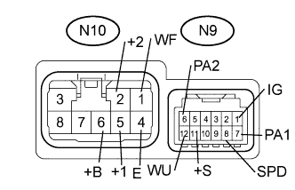
Standard Voltage Tester Connection Condition Specified Condition N10-6 (+B) - Body ground Always 20 to 28 V N9-1 (IG) - Body ground Ignition switch off→Ignition switch on Below 1 V → 20 to 28 V N10-1 (WF) - Body ground Ignition switch on, Washer switch off → Washer switch on 20 to 28 V → Below 1 V N10-2 (+2) - Body ground Ignition switch on, Wiper switch off → Wiper switch high position Below 1 V → 20 to 28 V N10-5 (+1) - Body ground Ignition switch on, Wiper switch off → Wiper switch low position Below 1 V → 20 to 28 V N9-6 (PA2) - Body ground Ignition switch on, Wiper switch not high position → Wiper switch high position 4.3 V or higher → Below 1 V N9-7 (PA1) - Body ground Ignition switch on, Wiper switch not low position → Wiper switch low position 4.3 V or higher → Below 1 V N9-8 (SPD) - Body ground Ignition switch on, Wiper switch not INT position → Wiper switch INT position 4.3 V or higher → Below 1 V N9-11 (+S) - Body ground Front wiper motor suspension → front wiper motor going Below 1 V → 5.5 V or higher N9-12 (WU) - Body ground Ignition switch on, Washer switch off → Washer switch on 4.3 V or higher → Below 1 V If the result is not as specified, replace the No. 1 integration relay.
-