ENGINE IMMOBILISER SYSTEM, Diagnostic DTC:B2796, B2798

| DTC Code | DTC Name |
|---|---|
| B2796 | No Communication in Immobiliser System |
| B2798 | Communication Malfunction No. 2 |
DESCRIPTION
These DTCs are stored if a key that does not have a transponder chip is inserted into the ignition key cylinder or if communication between the key and transponder key ECU is impossible.
| DTC Code | DTC Detection Condition | Trouble Area | DTC Output Confirmation Operation |
|---|---|---|---|
| B2796 | The key code cannot be transmitted (1 trip detection logic*). |
|
Insert the key into the ignition key cylinder. |
| B2798 | Key code identification cannot be completed within the specified time (1 trip detection logic*). |
|
Insert the key into the ignition key cylinder. |
-
*: Only output while a malfunction is present.
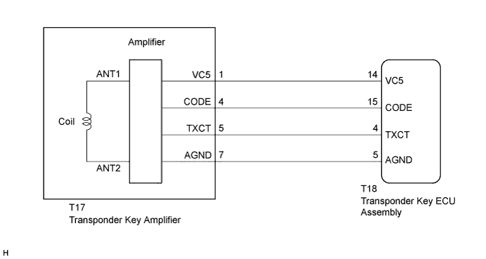
WIRING DIAGRAM
INSPECTION PROCEDURE
Note
-
When replacing the transponder key ECU assembly or key, refer to the Service Bulletin.
-
After performing repairs, perform the DTC output confirmation operation, and then confirm that no DTCs are output again.
PROCEDURE
-
CHECK WHETHER ENGINE STARTS WITH OTHER KEYS
-
Check if the engine starts with an already registered vehicle key.
OK Engine starts.
NG 
CHECK HARNESS AND CONNECTOR (TRANSPONDER KEY ECU - TRANSPONDER KEY AMPLIFIER) Click here
OK 
REREGISTER KEY CODE OR REPLACE KEY THAT CANNOT START ENGINE
-
-
CHECK HARNESS AND CONNECTOR (TRANSPONDER KEY ECU - TRANSPONDER KEY AMPLIFIER)
-
Disconnect the T18 transponder key ECU connector.
-
Disconnect the T17 transponder key amplifier connector.
-
Measure the resistance according to the value(s) in the table below.
Standard Resistance Tester Connection Condition Specified Condition T18-4 (TXCT) - T17-5 (TXCT) Always Below 1 Ω T18-5 (AGND) - T17-7 (AGND) Always Below 1 Ω T18-14 (VC5) - T17-1 (VC5) Always Below 1 Ω T18-15 (CODE) - T17-4 (CODE) Always Below 1 Ω T18-4 (TXCT) - Body ground Always 10 kΩ or higher T18-5 (AGND) - Body ground Always 10 kΩ or higher T18-14 (VC5) - Body ground Always 10 kΩ or higher T18-15 (CODE) - Body ground Always 10 kΩ or higher
NG 
REPAIR OR REPLACE HARNESS OR CONNECTOR
OK 
-
-
CHECK TRANSPONDER KEY ECU ASSEMBLY (VC5, AGND)
-
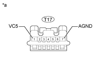
Text in Illustration *a Front view of wire harness connector
(to Transponder Key Amplifier)
Disconnect the T17 transponder key amplifier connector.
-
Measure the voltage according to the value(s) in the table below.
Standard Voltage Tester Connection Condition Specified Condition T17-1 (VC5) - Body ground No key in ignition key cylinder → Key inserted in ignition key cylinder 0 V → 5 V -
Measure the resistance according to the value(s) in the table below.
Standard Resistance Tester Connection Condition Specified Condition T17-7 (AGND) - Body ground Always Below 1 Ω
NG
REPLACE TRANSPONDER KEY ECU ASSEMBLY
OK
-
-
REPLACE TRANSPONDER KEY AMPLIFIER
-
Temporarily replace the transponder key amplifier with a new or normally functioning one Click here.
-
Clear the DTCs Click here.
NEXT
-
-
CHECK FOR DTC
-
Check for DTCs Click here.
OK DTC is not output.
NG
REPLACE TRANSPONDER KEY ECU ASSEMBLY
OK
END (TRANSPONDER KEY AMPLIFIER WAS DEFECTIVE)
-