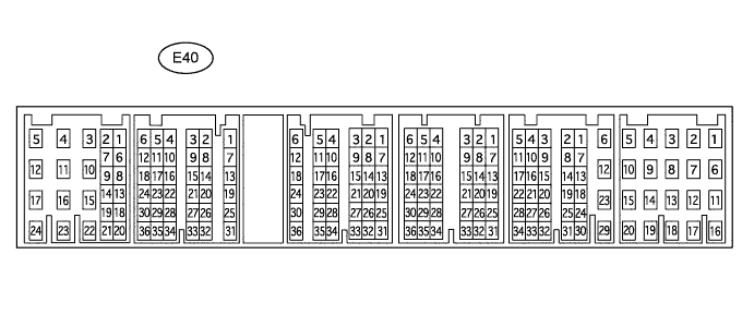
ENGINE IMMOBILISER SYSTEM TERMINALS OF ECU

-
CHECK TRANSPONDER KEY AMPLIFIER
-
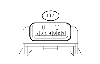
Disconnect the T17 transponder key amplifier connector.
-
Measure the resistance according to the value(s) in the table below.
Inspection with Ignition Switch Off Terminal No. (Symbol) Input/Output Wiring Color Terminal Description Condition Specified Condition Related Data List Item/DTC T17-7 (AGND) - Body ground - L - Body ground Ground Always Below 1 Ω -
-
If the result is not as specified, there may be a malfunction on the wire harness side.
-
-
Reconnect the T17 transponder key amplifier connector.
-
Measure the voltage according to the value(s) in the table below.
Inspection of Waveforms of Communication Signals between Transponder Key Amplifier and Transponder Key ECU Assembly Terminal No. (Symbol) Input/Output Wiring Color Terminal Description Condition Specified Condition Related Data List Item/DTC T17-1 (VC5) - T17-7 (AGND) Input V - L Transponder key amplifier power supply No key in ignition key cylinder → Key inserted in ignition key cylinder 0 V → Below 5.4 V → 0 V
-
BCC Malfunction
-
Abnormal Status
-
Different Encrypt Code
-
Different Serial Number
(If immobiliser key code certification communication is not performed correctly, the malfunction may be indicated by one or more of the Data List items listed above)
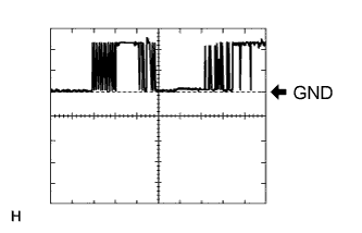
T17-4 (CODE) - T17-7 (AGND) Output LG - L Demodulated signal of key code data No key in ignition key cylinder Below 1 V Key inserted in ignition key cylinder Pulse generation (See waveform 1) T17-5 (TXCT) - T17-7 (AGND) Input P - L Key code output signal No key in ignition key cylinder Below 1 V Key inserted in ignition key cylinder Pulse generation (See waveform 2) -
-
Inspect using an oscilloscope.
Tech Tips
The waveform shown in the illustration is an example for reference only. Noise, chattering, etc. are not shown.
-
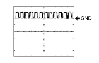
Waveform 1 (Reference)
Measurement Condition Item Content Tester Connection T17-4 (CODE) - T17-7 (AGND) Tool Setting 2.5 V/DIV., 20 ms./DIV. Condition Key inserted in ignition key cylinder -
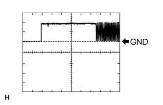
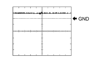
Waveform 2 (Reference)
Measurement Condition Item Content Tester Connection T17-5 (TXCT) - T17-7 (AGND) Tool Setting 2.5 V/DIV., 20 ms./DIV. Condition Key inserted in ignition key cylinder
-
-
-
CHECK TRANSPONDER KEY ECU ASSEMBLY
-
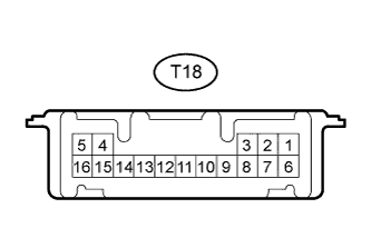
Disconnect the T18 transponder key ECU assembly connector.
-
Measure the resistance and voltage according to the value(s) in the table below.
Terminal No. (Symbol) Input/Output Wiring Color Terminal Description Condition Specified Condition Related Data List Item/DTC T18-16 (GND) - Body ground - W-B - Body ground Ground Always Below 1 Ω - T18-5 (AGND) - T18-16 (GND) - L - W-B Transponder key amplifier ground Always Below 1 Ω - T18-1 (+B) - T18-16 (GND) Input LG - W-B Battery Always 10 to 16 V +B T18-2 (IG) - T18-16 (GND) Input W - W-B Ignition switch Ignition switch off 0 V IG SW Ignition switch ON 10 to 16 V T18-3 (KSW) - T18-16 (GND) Input SB - W-B Unlock warning switch No key in ignition key cylinder 10 kΩ or higher Key SW/B2780 Key inserted in ignition key cylinder Below 1 Ω
-
If the result is not as specified, there may be a malfunction on the wire harness side.
-
-
Reconnect the T18 transponder key ECU assembly connector.
-
Measure the voltage according to the value(s) in the table below.
Terminal No. (Symbol) Input/Output Wiring Color Terminal Description Condition Specified Condition Related Data List Item/DTC T18-14 (VC5) - T18-16 (GND) Input V - W-B Transponder key amplifier power supply No key in ignition key cylinder → Key inserted in ignition key cylinder 0 V → Below 5.4 V → 0 V
-
BCC Malfunction
-
Abnormal Status
-
Different Encrypt Code
-
Different Serial Number
(If immobiliser key code certification communication is not performed correctly, the malfunction may be indicated by one or more of the Data List items listed above)
T18-4 (TXCT) - T18-16 (GND) Input P - W-B Key code output signal No key in ignition key cylinder Below 1 V Key inserted in ignition key cylinder Pulse generation (See waveform 1) T18-15 (CODE) - T18-16 (GND) Output LG - W-B Demodulated signal of key code data No key in ignition key cylinder Below 1 V Key inserted in ignition key cylinder Pulse generation (See waveform 2) T18-13 (EFIO) - T18-16 (GND) Input GR - W-B ECM output signal Ignition switch off Below 1 V E/G Start Permission Ignition switch ON Pulse generation (See waveform 3) T18-12 (EFII) - T18-16 (GND) Output Y - W-B ECM input signal Within 3 seconds after starter operates and initial combustion occurs, or within 3 seconds after ignition switch first turned to ON after battery disconnected and reconnected Pulse generation (See waveform 4) E/G Start Permission T18-3 (KSW) - T18-16 (GND) Input SB - W-B Unlock warning switch No key in ignition key cylinder 10 to 16 V Key SW/B2780 Key inserted in ignition key cylinder 0 V -
-
Inspect using an oscilloscope.
Tech Tips
The waveform shown in the illustration is an example for reference only. Noise, chattering, etc. are not shown.
-
Waveform 1 (Reference)
Measurement Condition Item Content Tester Connection T18-4 (TXCT) - T18-16 (GND) Tool Setting 2.5 V/DIV., 20 ms./DIV. Condition Key inserted in ignition key cylinder -
Waveform 2 (Reference)
Measurement Condition Item Content Tester Connection T18-15 (CODE) - T18-16 (GND) Tool Setting 2.5 V/DIV., 20 ms./DIV. Condition Key inserted in ignition key cylinder -
Waveform 3 (Reference)
Measurement Condition Item Content Tester Connection T18-13 (EFIO) - T18-16 (GND) Tool Setting 5 V/DIV., 100 ms./DIV. Condition Ignition switch ON -
Waveform 4 (Reference)
Measurement Condition Item Content Tester Connection T18-12 (EFII) - T18-16 (GND) Tool Setting 5 V/DIV., 100 ms./DIV. Condition Key inserted in ignition key cylinder
-
-
-
CHECK ECM
-
Measure the voltage according to the value(s) in the table below.
Terminal No. (Symbol) Wiring Color Terminal Description Condition Specified Condition E40-15 (IMO) - Body ground Y - Body ground Transponder key ECU assembly output signal Within 3 seconds after starter operates and initial combustion occurs, or within 3 seconds after ignition switch first turned ON after battery disconnected and reconnected Pulse generation (See waveform 1) E40-9 (IMI) - Body ground GR -Body ground Transponder key ECU assembly input signal Ignition switch off Below 1 V Ignition switch ON Pulse generation (See waveform 2) -
Inspect using an oscilloscope.
Tech Tips
The waveform shown in the illustration is an example for reference only. Noise, chattering, etc. are not shown.
-
Waveform 1 (Reference)
Measurement Condition Item Content Tester Connection E40-15 (IMO) - Body ground Tool Setting 5 V/DIV., 100 ms./DIV. Condition Key inserted in ignition key cylinder -
Waveform 2 (Reference)
Measurement Condition Item Content Tester Connection E40-9 (IMI) - Body ground Tool Setting 5 V/DIV., 100 ms./DIV. Condition Ignition switch ON
-
-