FRONT SEAT OUTER BELT ASSEMBLY INSTALLATION

Tech Tips
-
Use the same procedure for the RH and LH sides.
-
The procedure listed below is for the LH side.
-
INSTALL FRONT SHOULDER BELT ANCHOR ADJUSTER ASSEMBLY
-
Attach the guide.
-
Install the front shoulder belt anchor adjuster assembly with the 2 bolts.
- Torque:
- 42 N*m { 428 kgf*cm, 31 ft.*lbf }
-
-
INSTALL SHOULDER BELT ANCHORAGE PLATE COVER (for Semi-trim)
-
Attach the 4 hooks to install the shoulder belt anchorage plate cover to the shoulder belt anchor adjust cover.
-
-
INSTALL SHOULDER BELT ANCHOR ADJUST COVER (for Semi-trim)

-
Attach the 4 clips to install the shoulder belt anchor adjust cover.
-
-
INSTALL SHOULDER BELT ANCHORAGE PLATE COVER (for Full-trim)
-
Attach the 4 hooks to install the shoulder belt anchorage plate cover to the front quarter trim panel assembly LH.
-
-
INSTALL FRONT QUARTER TRIM PANEL ASSEMBLY LH (for Full-trim)
-
Attach the 5 clips to install the front quarter trim panel assembly LH.
-
-
INSTALL FRONT SEAT OUTER BELT ASSEMBLY LH
-
for Driver Side:
-
Check that the ignition switch is off.
-
Check that the cable is disconnected from the negative (-) battery terminal.
CAUTION:
Wait at least 90 seconds after disconnecting the cable from the negative (-) battery terminal to disable the SRS system.
-
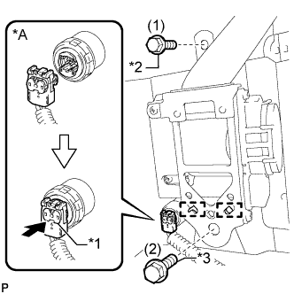
Text in Illustration *A for Driver Side *1 Lock Plate *2 Bolt A *3 Bolt B Attach the 2 guides and temporarily install the front seat outer belt assembly LH retractor with the 2 bolts A and B.
Note
When installing the front seat outer belt assembly LH retractor, make sure the guides of the vehicle only contact the installation areas of the front seat outer belt assembly LH retractor.
-
Tighten the 2 bolts in the order shown in the illustration.
- Torque:
- Bolt A
- 42 N*m { 428 kgf*cm, 31 ft.*lbf }
- Bolt B
- 8.5 N*m { 87 kgf*cm, 75 in.*lbf }
-
-
for Front Passenger Side:
-
Attach the 2 guides and temporarily install the front seat outer belt assembly RH retractor with the 2 bolts A and B.
Note
When installing the front seat outer belt assembly RH retractor, make sure the guides of the vehicle only contact the installation areas of the front seat outer belt assembly RH retractor.
-
Tighten the 2 bolts A and B.
- Torque:
- Bolt A
- 42 N*m { 428 kgf*cm, 31 ft.*lbf }
- Bolt B
- 8.5 N*m { 87 kgf*cm, 75 in.*lbf }
-
-
for Driver Side:
-
Connect the pretensioner connector to the front seat outer belt assembly LH retractor.
Note
When handling the pretensioner connector, take care not to damage the pretensioner wire harness.
-
Push in the lock plate to lock the pretensioner connector.
-
-
Temporarily connect the front seat outer belt assembly LH shoulder anchor with the bolt.
-
Temporarily connect the front seat outer belt assembly LH floor anchor with the bolt.
-
Check that the front seat outer belt assembly LH is not twisted.
-
Tighten the bolt to connect the front seat outer belt assembly LH shoulder anchor.
- Torque:
- 42 N*m { 428 kgf*cm, 31 ft.*lbf }
-
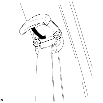
for Front Passenger Side:
Attach the 2 claws to close the shoulder anchor cover.
-

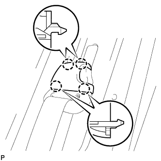
Text in Illustration *a 20° *b Vehicle Inside (0°) Tighten the bolt to connect the front seat outer belt assembly LH floor anchor.
- Torque:
- 42 N*m { 428 kgf*cm, 31 ft.*lbf }
Note
Install the front seat outer belt assembly LH so that the angle of the floor anchor is within the standard range.
Standard 0° to 20°
-
-
INSTALL SEAT BELT ANCHOR COVER CAP (for Driver Side)
-
Attach the 4 claws to install the seat belt anchor cover cap.
-
-
INSTALL LOWER QUARTER TRIM PANEL ASSEMBLY LH
-
Attach the 2 clips to install the lower quarter trim panel assembly LH.
-
-
INSTALL FRONT DOOR SCUFF PLATE LH
-
Install the front door scuff plate LH with the 4 screws.
-
-
CONNECT CABLE TO NEGATIVE BATTERY TERMINAL (for Driver Side)
Note
When disconnecting the cable, some systems need to be initialized after the cable is reconnected Click here.