SPIRAL CABLE INSPECTION

-
INSPECT SPIRAL CABLE SUB-ASSEMBLY
-
If any of the defects mentioned below are found, replace the spiral cable sub-assembly with a new one:
Scratches, cracks, dents or chips in the connector or spiral cable sub-assembly.
-
Check the spiral cable sub-assembly.
-
Set the spiral cable sub-assembly to the center position Click here.
-
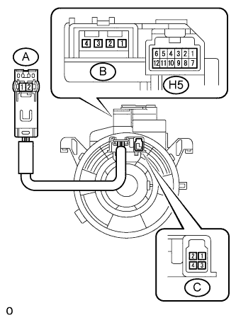
After setting the spiral cable sub-assembly to the center position, rotate the spiral cable sub-assembly clockwise 4 times and measure the resistance according to the value(s) in the table below.
Note
Do not turn the spiral cable sub-assembly by the airbag wire harness.
Standard Resistance Tester Connection Condition Specified Condition A-1 - B-2 Always Below 1 Ω A-2 - B-1 Always Below 1 Ω H5-1 - C3 Always Below 1 Ω H5-2 - C4 Always Below 1 Ω H5-8 - C2 Always Below 1 Ω If the results are not as specified, replace the spiral cable sub-assembly.
-
After setting the spiral cable sub-assembly to the center position, rotate the spiral cable sub-assembly clockwise 4 times. Then, while rotating the spiral cable sub-assembly counterclockwise 8 times and measure the resistance according to the value(s) in the table below.
Note
Do not turn the spiral cable sub-assembly by the airbag wire harness.
Standard Resistance Tester Connection Condition Specified Condition A-1 - B-2 Always Below 1 Ω A-2 - B-1 Always Below 1 Ω H5-1 - C3 Always Below 1 Ω H5-2 - C4 Always Below 1 Ω H5-8 - C2 Always Below 1 Ω If the results are not as specified, replace the spiral cable sub-assembly.
Note
As the spiral cable sub-assembly may break, do not rotate the spiral cable sub-assembly more than the specified amount.
-
-