N04C-US COMPRESSOR REASSEMBLY

-
INSTALL MAGNET CLUTCH ASSEMBLY
-
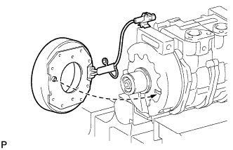
Install the magnet clutch stator while aligning the protrusion on the stator with the notch on the compressor as shown in the illustration.
-

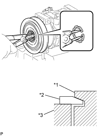
Text in Illustration *1 Compressor Assembly *2 Snap Ring *3 Magnet Clutch Stator Using a snap ring expander, install a new snap ring with the chamfered side facing up.
Note
Take care not to damage the seal cover of the bearing when installing the snap ring.
-
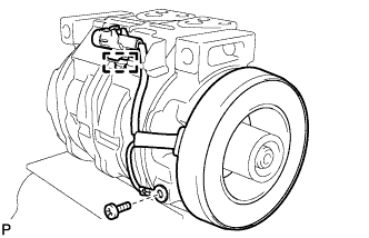
Install the ground wire with the screw.
-
Attach the clamp.
-
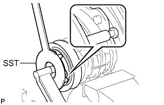
Text in Illustration *1 Compressor Assembly *2 Snap Ring *3 Magnet Clutch Rotor Using a snap ring expander, install the magnet clutch rotor and a new snap ring with the chamfered side facing up.
Note
-
Do not expand the snap ring by more than 30.5 mm (1.20 in.) when installing it.
-
Do not damage the seal cover of the bearing when installing the snap ring.
-
-
Install the magnet clutch washer and magnet clutch hub.
Note
Do not change the combination of the magnet clutch washers used before disassembly.
-
Using SST, install the bolt.
- SST
- 09985-00270
- Torque:
- 18 N*m { 184 kgf*cm, 13 ft.*lbf }
Note
Make sure that there is no foreign matter or oil on the compressor shaft, bolt, and clutch hub.
-
-
INSPECT MAGNET CLUTCH CLEARANCE
-
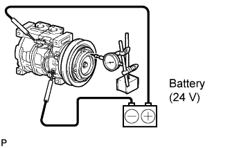
Set the dial indicator to the pressure plate of the magnet clutch.
-
Connect the magnet clutch lead wire to the positive terminal of the battery.
-
Inspect the clearance between the pressure plate and rotor when connecting the negative terminal to the battery.
Standard clearance value 0.35 to 0.60 mm (0.0138 to 0.0236 in.) Tech Tips
If the clearance is not within the standard value, adjust it using shims to obtain the standard one.
Shim thickness mm in. 0.1 0.00394 0.3 0.0118 0.5 0.0220
-
-
ADJUST COMPRESSOR OIL LEVEL
-
When replacing the compressor and magnet clutch with a new one, gradually discharge the inert gas (helium) from the service valve, and drain the following amount of oil from the new compressor and magnet clutch before installation.
Standard (Oil capacity inside the new compressor with magnet clutch: 120 + 15 cc (4.2 + 0.51 fl. oz.) ) - (Remaining oil amount in the removed compressor with magnet clutch) = (Oil amount to be removed from the new compressor when replacing) Note
-
When checking the compressor oil level, observe the precautions on the cooler removal/installation.
-
If a new compressor with magnet clutch is installed without removing some oil, due to the oil remaining in the pipes of the vehicle, the oil amount will be too large. This prevents heat exchange in the refrigerant cycle and causes refrigerant failure.
-
If the volume of oil remaining in the removed compressor with magnet clutch is too small, check for oil leakage.
-
Be sure to use ND-OIL 8 or equivalent for compressor oil.
-
-