AIRBAG SYSTEM SRS Warning Light Remains ON
DESCRIPTION
The SRS warning light is located on the combination meter assembly.
When the SRS is normal, the SRS warning light comes on for approximately 6 seconds after the ignition switch is turned from off to ON, and then goes off automatically.
If there is a malfunction in the SRS, the SRS warning light comes on or blinks* to inform the driver of the problem.
The SRS is equipped with a voltage-increase circuit (DC-DC converter) in the airbag ECU assembly in case the source voltage drops.
When the battery voltage drops, the voltage-increase circuit (DC-DC converter) functions to increase the voltage of the SRS to the normal voltage.
A malfunction in this circuit is not recorded in the airbag ECU assembly. The SRS warning light automatically goes off when the source voltage returns to normal.
-
*: If the SRS warning light blinks, replace the airbag ECU assembly with a new one.
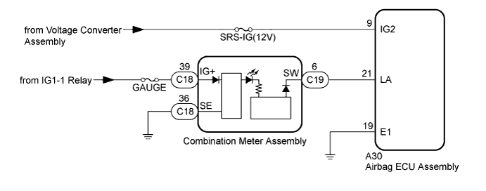
WIRING DIAGRAM
INSPECTION PROCEDURE
Note
-
If the DTC B1662 is output, troubleshoot the DTC first Click here.
-
After turning the ignition switch off, waiting time may be required before disconnecting the cable from the battery terminal. Therefore, make sure to read the disconnecting the cable from the battery terminal notices before proceeding with work Click here.
-
When disconnecting the cable from the negative (-) battery terminal while performing repairs, some systems need to be initialized after the cable is reconnected Click here.
-
Inspect the fuses for circuits related to this system before performing the following inspection procedure.
Tech Tips
-
When trouble code B1662 is output, first perform troubleshooting for it.
-
Inspect the fuses for circuits related to this system before performing the following inspection procedure.
PROCEDURE
-
CHECK BATTERY
-
Measure the voltage of the battery.
Standard voltage 20 to 28 V
NG 
REPLACE OR RECHARGE BATTERY
OK 
-
-
CHECK CONNECTION OF CONNECTORS
-
Turn the ignition switch off.
-
Disconnect the cable from the negative (-) battery terminal, and wait at least 90 seconds.
-
Check that the connectors are properly connected to the airbag ECU assembly and combination meter assembly.
OK The connectors are properly connected.
NG
CONNECT CONNECTORS PROPERLY
OK
-
-
CHECK CONNECTORS
-
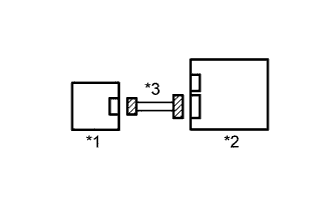
Text in Illustration *1 Combination Meter Assembly *2 Airbag ECU Assembly *3 Instrument Panel Wire Disconnect the connectors from the airbag ECU assembly and combination meter assembly.
-
Check that the connectors (on the airbag ECU assembly side and combination meter assembly side) are not damaged.
OK The connectors are not deformed or damaged.
NG
REPLACE INSTRUMENT PANEL WIRE
OK
-
-
CHECK HARNESS AND CONNECTOR (AIRBAG ECU ASSEMBLY - BATTERY AND BODY GROUND)
-
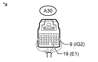
Text in Illustration *a Rear view of wire harness connector
(to Airbag ECU Assembly)
Connect the connectors to the combination meter assembly.
-
Measure the resistance according to the value(s) in the table below.
Standard Resistance Tester Connection Condition Specified Condition A30-19 (E1) - Body ground Always Below 1 Ω -
Connect the cable to the negative (-) battery terminal, and wait at least 2 seconds.
-
Turn the ignition switch to ON, and wait at least 60 seconds.
-
Operate all the components of the electrical system (wipers, headlights, etc.).
-
Measure the voltage according to the value(s) in the table below.
Standard Voltage Tester Connection Switch Condition Specified Condition A30-9 (IG2) - A30-19 (E1) Ignition switch off Below 1 V A30-9 (IG2) - A30-19 (E1) Ignition switch ON 11 to 14 V
NG
REPLACE INSTRUMENT PANEL WIRE
OK
-
-
CHECK HARNESS AND CONNECTOR (COMBINATION METER ASSEMBLY - BATTERY AND BODY GROUND)
-
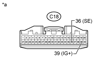
Text in Illustration *a Front view of wire harness connector
(to Combination Meter Assembly)
Turn the ignition switch off.
-
Disconnect the cable from the negative (-) battery terminal, and wait at least 90 seconds.
-
Disconnect the connector from the combination meter assembly.
-
Connect the connector to the airbag ECU assembly.
-
Measure the resistance according to the value(s) in the table below.
Standard Resistance Tester Connection Condition Specified Condition C18-36 (SE) - Body ground Always Below 1 Ω -
Connect the cable to the negative (-) battery terminal, and wait at least 2 seconds.
-
Turn the ignition switch to ON, and wait at least 60 seconds.
-
Measure the voltage according to the value(s) in the table below.
Standard Voltage Tester Connection Switch Condition Specified Condition C18-39 (IG+) - C18-36 (SE) Ignition switch off Below 1 V C18-39 (IG+) - C18-36 (SE) Ignition switch ON 11 to 14 V
NG
REPLACE HARNESS AND CONNECTOR
OK
-
-
CHECK HARNESS AND CONNECTOR (AIRBAG ECU ASSEMBLY - COMBINATION METER ASSEMBLY)
-
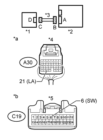
Text in Illustration *1 Combination Meter Assembly *2 Airbag ECU Assembly *3 Instrument Panel Wire *4 Connector B *5 Connector C *a Rear view of wire harness connector
(to Airbag ECU Assembly)
*b Front view of wire harness connector
(to Combination Meter Assembly)
Turn the ignition switch off.
-
Disconnect the cable from the negative (-) battery terminal, and wait at least 90 seconds.
-
Disconnect the connector from the airbag ECU assembly.
-
Measure the resistance according to the value(s) in the table below.
Standard Resistance Tester Connection Condition Specified Condition A30-21 (LA) - C19-6 (SW) Always Below 1 Ω -
Connect the cable to the negative (-) battery terminal, and wait at least 2 seconds.
-
Turn the ignition switch to ON, and wait at least 60 seconds.
-
Measure the resistance according to the value(s) in the table below.
Standard Resistance Tester Connection Condition Specified Condition A30-21 (LA) - Body ground Always 1 MΩ or higher C19-6 (SW) - Body ground Always 1 MΩ or higher
NG
REPLACE INSTRUMENT PANEL WIRE
OK
-
-
CHECK AIRBAG ECU ASSEMBLY
-
Connect the connector to the airbag ECU assembly.
-
Connect the cable to the negative (-) battery terminal, and wait at least 2 seconds.
-
Turn the ignition switch to ON.
-
Measure the voltage according to the value(s) in the table below.
Standard Voltage Tester Connection Switch Condition Specified Condition C19-6 (SW) - Body ground Within 6 seconds after the ignition switch turned to ON Below 1 V C19-6 (SW) - Body ground 6 seconds elapsed after the ignition switch turned to ON 11 to 14 V
NG
REPLACE COMBINATION METER ASSEMBLY Click here
OK
-
-
CHECK AIRBAG ECU ASSEMBLY
-
Turn the ignition switch off.
-
Disconnect the cable from the negative (-) battery terminal, and wait at least 90 seconds.
-
Temporarily replace the airbag ECU assembly with a new one Click here.
-
Connect the cable to the negative (-) battery terminal, and wait at least 2 seconds.
-
Turn the ignition switch to ON.
-
Check the SRS warning light condition.
OK After the primary check period, the SRS warning light goes off for approximately 10 seconds and then remains on. Tech Tips
The primary check period is approximately 6 seconds after the ignition switch is turned to ON.
NG
REPLACE COMBINATION METER ASSEMBLY Click here
OK 
END (AIRBAG ECU ASSEMBLY WAS DEFECTIVE)
-