AIR CONDITIONING UNIT INSTALLATION

Tech Tips
A bolt without a torque specification is shown in the standard bolt chart Click here.
-
INSTALL NO. 1 AIR CONDITIONING AMPLIFIER ASSEMBLY
-
Install the No. 1 air conditioning amplifier assembly with the bolt.
- Torque:
- 1.9 N*m { 19 kgf*cm, 17 in.*lbf }
-
-
INSTALL NO. 1 AIR DUCT SUB-ASSEMBLY
-
Attach the 2 claws to install the No. 1 air duct sub-assembly.
-
-
INSTALL NO. 2 AIR DUCT SUB-ASSEMBLY
-
Attach the 2 claws to install the No. 2 air duct sub-assembly.
-
-
INSTALL LOWER DEFROSTER NOZZLE
-
Attach the 4 claws to install the lower defroster nozzle.
-
-
INSTALL HEATER TO REGISTER DUCT ASSEMBLY
-
Attach the 4 claws to install the heater to register duct assembly.
-
-
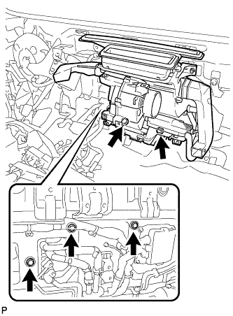
INSTALL AIR CONDITIONING UNIT ASSEMBLY
-
Temporarily tighten the air conditioning unit assembly with the 5 bolts.
-
-
INSTALL NO. 1 COOLER UNIT DRAIN HOSE
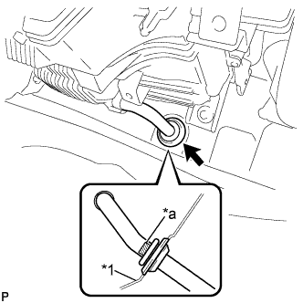
Text in Illustration *1 Floor *a Marking
-
Attach the clamp.
-
Install the grommet as shown in the illustration.
Note
Make sure not to twist the cooler unit drain hose when installing it.
-
-
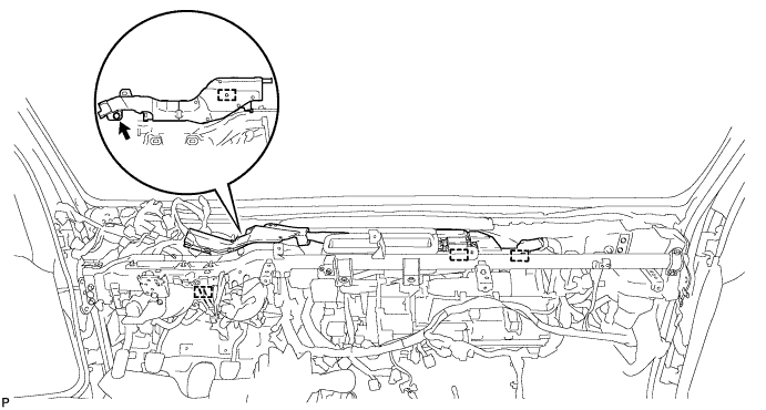
INSTALL HEATER WIRE
-
Connect the connectors and attach the 3 clamps, then install the heater wire.
-
-
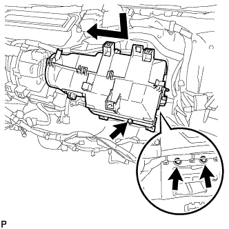
INSTALL AIR DAMPER CASE ASSEMBLY
-
Temporarily tighten the air damper case assembly with the 4 bolts.
-
Connect the connectors and attach the 4 clamps, then install the wire harness.
-
-
INSTALL NO. 2 AIR DUCT SEAL
-
Install the No. 2 air duct seal with the 2 clips.
-
-
INSTALL NO. 1 AIR DUCT SEAL
-
Install the No. 1 air duct seal with the 2 clips.
-
-
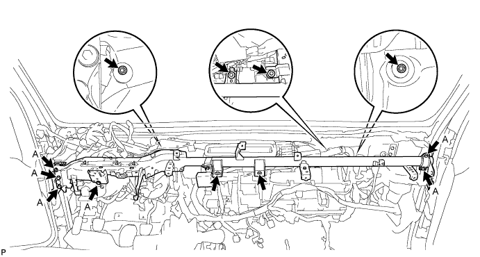
INSTALL INSTRUMENT PANEL REINFORCEMENT
-
Temporarily tighten the instrument panel reinforcement with the 10 bolts and 2 nuts.
-
Tighten the 6 bolts A and the 2 nuts.
-
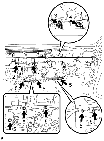
Tighten the 12 bolts in the order shown in the illustration.
- Torque:
- 6.0 N*m { 61 kgf*cm, 53 in.*lbf }
-
Connect the connectors and attach the 4 clamps, then install the wire harness.
-
Install the wire harness protector with the bolt.
- Torque:
- 6.0 N*m { 61 kgf*cm, 53 in.*lbf }
-
-
INSTALL BRAKE MASTER CYLINDER RESERVOIR ASSEMBLY
-
Install the brake master cylinder reservoir assembly with the bolt.
-
-
INSTALL NO. 1 INSTRUMENT PANEL BRACE SUB-ASSEMBLY
-
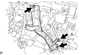
Install the No. 1 instrument panel brace sub-assembly with the 3 bolts.
- Torque:
- Bolt A
- 6.0 N*m { 61 kgf*cm, 53 in.*lbf }
-
-
INSTALL NO. 4 AIR DUCT SUB-ASSEMBLY
-
Attach the 2 claws to install No. 4 air duct sub-assembly.
-
Install the 2 clips.
-
-
INSTALL NO. 3 AIR DUCT SUB-ASSEMBLY
-
Attach the 2 guides to 2 claws, then install the No. 3 air duct sub-assembly.
-
Install the 2 clips.
-
-
INSTALL ECU BRACKET
-
Install the ECU bracket with the 3 bolts.
- Torque:
- 6.0 N*m { 61 kgf*cm, 53 in.*lbf }
-
-
INSTALL ECU BRACKET
-
Install the ECU bracket with the 3 bolts.
- Torque:
- 6.0 N*m { 61 kgf*cm, 53 in.*lbf }
-
-
INSTALL STEERING COLUMN ASSEMBLY
-
INSTALL INSTRUMENT PANEL SUB-ASSEMBLY
-
CONNECT COOLER REFRIGERANT SUCTION PIPE A
-
Remove the vinyl tape from cooler refrigerant suction pipe A and the connecting portion of the air conditioner unit.
-
Apply sufficient compressor oil to a new O-ring and the connecting part of the cooler refrigerant suction pipe A.
Compressor oil ND-OIL8 or equivalent -
Install the O-ring to the cooler refrigerant suction pipe A.
Note
Keep the O-ring and O-ring fitting surfaces clean from dirt or any foreign objects.
-
Connect the cooler refrigerant suction pipe A to the air conditioner unit assembly with the bolt.
- Torque:
- 5.4 N*m { 55 kgf*cm, 48 in.*lbf }
-
-
CONNECT COOLER REFRIGERANT LIQUID PIPE A
-
Remove the vinyl tape from cooler refrigerant liquid pipe A and the connecting portion of the air conditioner unit.
-
Apply sufficient compressor oil to a new O-ring and the connecting part of the cooler refrigerant liquid pipe A.
Compressor oil ND-OIL8 or equivalent -
Install the O-ring to the cooler refrigerant liquid pipe A.
Note
Keep the O-ring and O-ring fitting surfaces clean from dirt or any foreign objects.
-
Connect the cooler refrigerant liquid pipe A to the air conditioner unit with the bolt.
- Torque:
- 5.4 N*m { 55 kgf*cm, 48 in.*lbf }
-
-
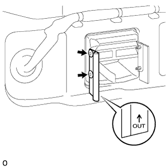
INSTALL HEATER WATER INLET HOSE C
-
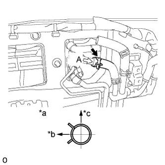
Text in Illustration *a View A *b Front Side *c Upper Side Connect the heater water inlet hose C, and then install the clip in the location shown in the illustration.
Note
Do not apply excessive force to the heater water inlet hose C.
-
-
INSTALL HEATER WATER OUTLET HOSE C
-
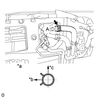
Text in Illustration *a View A *b Front Side *c Upper Side Connect the heater water outlet hose C, and then install the clip in the location shown in the illustration.
Note
Do not apply excessive force to the heater water outlet hose C.
-
-
ADD ENGINE COOLANT
CAUTION:
Do not remove the radiator cap sub-assembly, radiator drain cock plug or engine drain plug while the engine and radiator are still hot. Pressurized, hot engine coolant and steam may be released and cause serious burns.
Note
Do not substitute plain water for engine coolant.
-
Add engine coolant.
Standard capacity 14.2 liters (15.0 US qts, 12.5 Imp. qts) Tech Tips
TOYOTA vehicles are filled with TOYOTA SLLC at the factory. In order to avoid damage to the engine cooling system and other technical problems, only use TOYOTA SLLC or similar high quality ethylene glycol based non-silicate, non-amine, non-nitrite, non-borate coolant with long-life hybrid organic acid technology (coolant with long-life hybrid organic acid technology is a combination of low phosphates and organic acids).
-
Check the coolant level inside the radiator by squeezing the inlet radiator hose and outlet radiator hose several times by hand. If the coolant level goes down, add coolant.
-
Install the radiator cap sub-assembly.
-
Slowly pour coolant into the radiator reservoir until it reaches the F line.
-
Bleed air from the cooling system.
-
Warm up the engine until the thermostat opens.
While the thermostat is open, circulate the coolant for several minutes.
-
Maintain the engine speed at a speed between 2500 and 3000 rpm.
-
Press the inlet and outlet radiator hoses several times by hand to bleed air.
Note
-
Wear protective gloves.
-
Be careful as the radiator hoses are hot.
-
Keep your hands away from the radiator fan.
-
-
-
Stop the engine and wait until the coolant cools down to ambient temperature.
-
Remove the radiator cap sub-assembly and check the coolant level.
If the coolant level has dropped, add coolant.
-
Check the coolant level inside the radiator reservoir assembly again.
If the coolant level is below the F line, add coolant to F line.
-
-
INSPECT FOR COOLANT LEAK
CAUTION:
Do not remove the radiator cap while the engine and radiator are still hot. Pressurized, hot engine coolant and steam may be released and cause serious burns.
Note
Before each inspection, turn the A/C switch off.
-
Fill the radiator with coolant and attach a radiator cap tester.
-
Warm up the engine.
-
Using the radiator cap tester, increase the pressure inside the radiator to 137 kPa (1.4 kgf/cm2, 20 psi), and check that the pressure does not drop.
If the pressure drops, check the hoses, radiator assembly and engine water pump for leaks. If no external leaks are found, check the heater core, cylinder block and cylinder head.
-
-
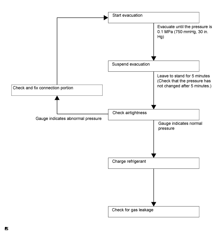
CHARGE REFRIGERANT
Tech Tips
Charge refrigerant in accordance with the equipment manual.
-
Perform vacuum purging using a vacuum pump.
-
Charge refrigerant HFC-134a (R134a).
- SST
- 09985-20010 ( 09985-02010, 09985-02050, 09985-02060, 09985-02070, 09985-02080, 09985-02090, 09985-02110, 09985-02130, 09985-02140, 09985-02150 )
Standard charge amount 350 to 450 g (12.3 to 15.9 oz.) Note
Do not start the engine before charging it with refrigerant as the cooler compressor does not work properly without sufficient refrigerant. This could cause the compressor to overheat.
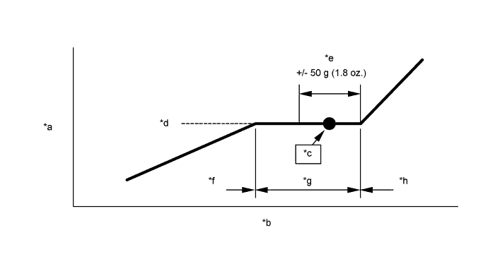
Text in Illustration *a High Pressure *b Charge Amount *c Regulation amount *d Bubble disappearing point in sight glass. *e Refrigerant margin *f Low charge *g Proper amount *h High charge Tech Tips
-
The relationship between the refrigerant charge amount and the pressure is as follows.
-
High Charge Range:
If the refrigerant is overcharged, the pressure rises on the high-pressure side. High-pressure cut off frequently occurs. This causes insufficient cooling performance and also insufficient compressor lubrication.
-
Low Charge Range:
A shortage of refrigerant causes insufficient cooling performance and low circulation of refrigerant oil, which shortens the compressor life. Operation with insufficient coolant raises the refrigerant temperature and causes heat deterioration of the rubber seals and hoses. Cracking and subsequent refrigerant leakage may occur.
-
Install the caps onto the service valves on the refrigerant line.
-
-
WARM UP ENGINE
Note
Warm up the engine at less than 2000 rpm for 1 minute or more after charging it with refrigerant.
-
INSPECT LEAKAGE OF REFRIGERANT
-
After recharging the refrigerant gas, check for refrigerant gas leakage using a halogen leak detector.
-
Perform the operation as follows:
-
Stop the engine.
-
Secure good ventilation (the halogen leak detector may react to volatile gases other than refrigerant, such as evaporated gasoline or exhaust gas).
-
Repeat the test 2 or 3 times.
-
Make sure that some refrigerant remains in the refrigeration system.
When the compressor is off: approximately 392 to 588 kPa (4 to 6 kgf/cm2, 57 to 85 psi)
Tech Tips
It is impossible for the above pressure to be maintained if there is leakage.
-
-
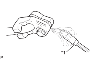
Text in Illustration *1 Halogen Leak Detector Using the halogen leak detector, check the refrigerant line, especially at the connection points, for leakage.
-
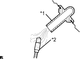
Text in Illustration *1 Drain Hose *2 Halogen Leak Detector Bring the halogen leak detector close to the drain hose before performing the test.
Tech Tips
-
After the blower motor has stopped, leave the cooling unit for at least 15 minutes.
-
Place the halogen leak detector sensor under the drain hose.
-
When bringing the halogen leak detector close to the drain hose, make sure that the halogen leak detector does not react to other volatile gases.
If such a reaction is unavoidable, the vehicle must be lifted up.
-
-
If no gas leakage is detected from the drain hose, remove the blower motor from the cooling unit. Insert the halogen leak detector sensor into the unit and perform the test.
-
Disconnect the pressure switch connector and leave it for approximately 20 minutes. Bring the halogen leak detector close to the pressure switch and perform the test.
-
-
INSTALL COWL TOP OUTER PANEL SUB-ASSEMBLY
-
INSTALL HEADLIGHT ASSEMBLY RH