POWER STEERING GEAR INSTALLATION

-
INSTALL STUD BOLT
-
Temporarily install the 2 stud bolts to the power steering gear assembly.
-
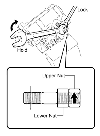
Install the 2 nuts to the stud bolt.
Recommended service nut Thread diameter 14.0 mm (0.551 in.) Thread pitch 1.5 mm (0.059 in.) -
Lock the upper nut using the lower nut.
-
Turn the upper nut and tighten the stud bolt to the power steering gear assembly.
- Torque:
- 10 N*m { 102 kgf*cm, 7 ft.*lbf }
Note
Install the stud bolt securely until the threads are completely screwed into the power steering gear assembly.
-
-
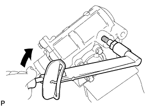
INSTALL POWER STEERING GEAR ASSEMBLY
-
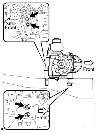
Install the power steering gear assembly with the 2 bolts, 2 nuts and 2 washers.
- Torque:
- 180 N*m { 1835 kgf*cm, 133 ft.*lbf }
Note
Be careful not to drop the power steering gear assembly because it is extremely heavy.
-
-
INSTALL PITMAN ARM
-
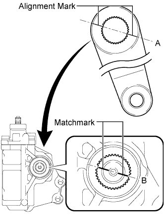
Align the matchmarks on the sector shaft and the alignment marks on the pitman arm.
Tech Tips
Make sure to align the center of the missing tooth of the pitman arm (A) and the center of the missing tooth of the sector shaft (B) when installing the pitman arm to the steering gear assembly.
-
Install the spring washer and the sector shaft to the pitman arm setting hexagon nut.
- Torque:
- 320 N*m { 3263 kgf*cm, 236 ft.*lbf }
-
-
CONNECT STEERING DRAG LINK ASSEMBLY
-
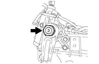
Connect the drag link to the pitman arm with the nut.
- Torque:
- 195 N*m { 1988 kgf*cm, 144 ft.*lbf }
-
Install a new cotter pin.
Note
Further tighten the nut to 30° if the holes for the cotter pin are not aligned.
-
-
CONNECT PRESSURE FEED HOSE
-
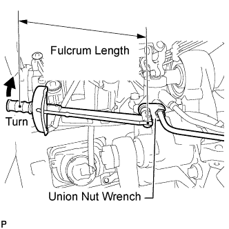
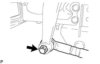
Using union nut wrench, connect the pressure feed hose to the power steering gear assembly.
- Torque:
- 44 N*m { 449 kgf*cm, 32 ft.*lbf }
Note
Use the formula to calculate special torque values for situations where a union nut wrench is combined with a torque wrench Click here.
-
-
CONNECT STEERING GEAR OUTLET RETURN TUBE
-
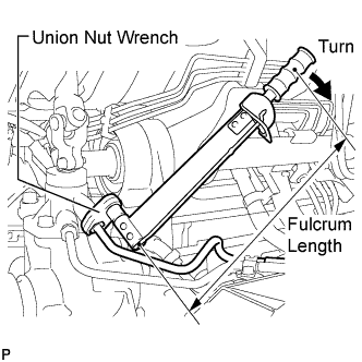
Using union nut wrench, connect the steering gear outlet return tube to the power steering gear assembly.
- Torque:
- 44 N*m { 449 kgf*cm, 32 ft.*lbf }
Note
Use the formula to calculate special torque values for situations where a union nut wrench is combined with a torque wrench Click here.
-
-
ALIGN FRONT WHEELS FACING STRAIGHT AHEAD
-
CONNECT STEERING MAIN SHAFT ASSEMBLY
-
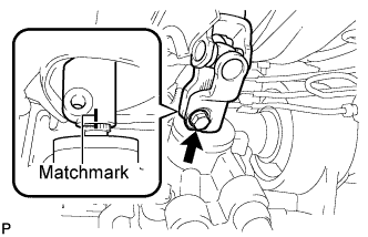
Align the matchmarks on the steering main shaft assembly and the power steering gear assembly.
-
Install the bolt.
- Torque:
- 35 N*m { 357 kgf*cm, 26 ft.*lbf }
-
-
ADD POWER STEERING FLUID
-
BLEED POWER STEERING SYSTEM
-
Check the fluid level Click here.
-
Jack up the front of the vehicle and support it with stands.
-
Turn the steering wheel.
-
With the engine stopped, turn the steering wheel slowly from lock to lock several times.
-
-
Lower the vehicle.
-
Start the engine.
-
Run the engine at idle for a few minutes.
-
-
Turn the steering wheel.
-
With the engine idling, turn the steering wheel left or right to the full lock position and keep it in that position for 2 to 3 seconds, then turn the steering wheel to the opposite full lock position and keep it there for 2 to 3 seconds (*1).
-
Repeat this procedure (*1) several times.
-
-
Stop the engine.
-
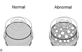
Check for foaming or emulsification.
Tech Tips
If the system has to be bled twice because of forming or emulsification, be sure to check for fluid leaks in the system.
-
Check the fluid level Click here.
-
-
CHECK POWER STEERING FLUID LEVEL
-
Keep the vehicle level.
-
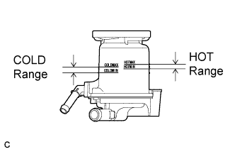
With the engine stopped, check the fluid level in the fluid reservoir.
If necessary, add fluid.
Fluid ATF DEXRON II or III, or equivalent. Tech Tips
If the fluid is hot, check that the fluid level is within the HOT range on the fluid reservoir. If the fluid is cold, check that the fluid level is within the COLD range.
-
Start the engine and run it at idle.
-
Turn the steering wheel from lock to lock several times to raise fluid temperature.
Fluid temperature 50 to 60°C (122 to 140°F) -
Check for foaming or emulsification.
If foaming or emulsification is identified, bleed the power steering system Click here.
-
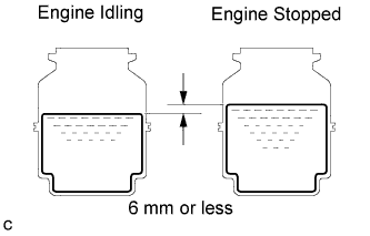
With the engine idling, measure the fluid level in the fluid reservoir.
-
Stop the engine.
-
Wait a few minutes and remeasure the fluid level in the fluid reservoir.
Maximum fluid level rise 6 mm (0.24 in.) If any problem is found, bleed the power steering system Click here.
-
Check the fluid level.
-
-
INSPECT FOR POWER STEERING FLUID LEAK
-
INSTALL HEADLIGHT ASSEMBLY LH
-
INSTALL CLEARANCE LIGHT ASSEMBLY LH
-
INSTALL RADIATOR GRILLE
-
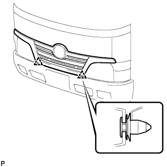
Engage the 2 clips and install the radiator grille assembly.
-
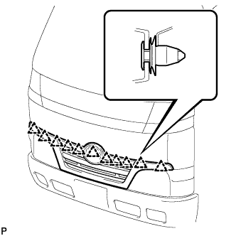
Engage the 11 clips.
-
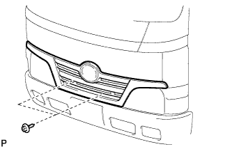
Install the 2 screws.
-
-
HEADLIGHT AIMING ADJUSTMENT
(See Pub. No. RM1008E, page 65-13.)