STEERING COLUMN ASSEMBLY INSTALLATION

-
INSTALL STEERING POST ASSEMBLY
-
Temporarily install the steering post assembly with the 4 bolts.
Note
Make sure that the steering column tube cover is not twisted.
-
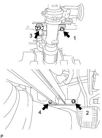
Fully tighten the 4 bolts in the order shown in the illustration.
- Torque:
- 12 N*m { 117 kgf*cm, 8 ft.*lbf }
-
Install the 4 bolts to install the steering post assembly.
-
-
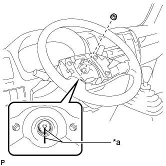
CONNECT STEERING MAIN SHAFT ASSEMBLY
-
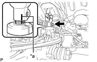
Text in Illustration *a Matchmark Align the matchmarks on the steering main shaft assembly and the power steering gear assembly.
-
Connect the steering main shaft assembly to the power steering gear assembly.
-
Install the bolt.
- Torque:
- 35 N*m { 357 kgf*cm, 26 ft.*lbf }
-
-
INSTALL HEADLIGHT DIMMER SWITCH ASSEMBLY
-
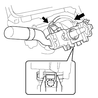
While loosening the band clamp, attach the claw to install the headlight dimmer switch assembly.
-
Connect the connector.
-
-
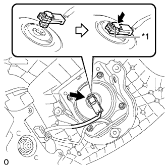
INSTALL SPIRAL CABLE SUB-ASSEMBLY
-
Attach the 3 claws to install the spiral cable sub-assembly.
-
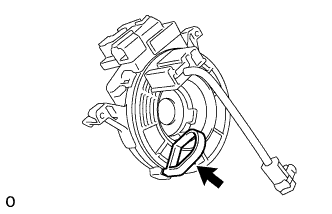
If installing a new spiral cable sub-assembly:
Remove the lock pin.
-
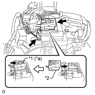
Connect the connector to the spiral cable sub-assembly.
-
Connect the airbag connector (yellow colored) to the spiral cable sub-assembly.
Text in Illustration *1 Lock Slider *2 Airbag Connector (Yellow Colored) *a Lock Position Note
When handling the airbag connector, take care not to damage the airbag wire harness.
-
Check that the lock slider is in the lock position.
-
-
INSTALL WINDSHIELD WIPER SWITCH ASSEMBLY
-
Attach the claw to install the windshield wiper switch assembly.
-
Connect the connector.
-
-
INSTALL UPPER STEERING COLUMN COVER
-
Engage the 3 claws and install the steering column cover plate.
-
Install the upper steering column cover onto the steering column.
-
-
INSTALL LOWER STEERING COLUMN COVER
-
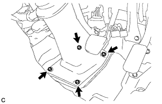
Engage the 4 claws and install the lower steering column cover.
-
Install the 5 screws.
-
-
ADJUST SPIRAL CABLE SUB-ASSEMBLY
-
Check that the ignition switch is off.
-
Check that the cable is disconnected from the negative (-) battery terminal.
CAUTION:
Wait at least 90 seconds after disconnecting the cable from the negative (-) battery terminal to disable the SRS system.
-
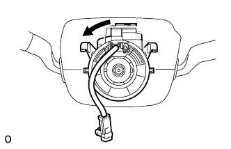
Rotate the spiral cable sub-assembly counterclockwise slowly by hand until it feels firm.
Note
Do not turn the spiral cable sub-assembly by the airbag wire harness.
-
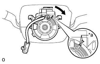
Text in Illustration *a Alignment Mark Rotate the spiral cable sub-assembly clockwise approximately 4 turns to align the alignment marks.
Note
Do not turn the spiral cable sub-assembly by the airbag wire harness.
Tech Tips
The spiral cable sub-assembly can be rotated approximately 4 turns both clockwise and counterclockwise from the center position.
-
-
PLACE FRONT WHEELS FACING STRAIGHT AHEAD
-
INSTALL STEERING WHEEL COVER SUB-ASSEMBLY
-
Install the 3 screws and steering wheel cover sub-assembly to the steering wheel assembly.
-
-
INSTALL STEERING WHEEL ASSEMBLY
-
Text in Illustration *a Matchmark Align the matchmarks on the steering wheel assembly and steering main shaft assembly.
-
Install the steering wheel assembly set nut.
- Torque:
- 50 N*m { 510 kgf*cm, 37 ft.*lbf }
-
-
INSPECT STEERING WHEEL CENTER POINT
-
INSTALL STEERING PAD
-
Check that the ignition switch is off.
-
Check that the cable is disconnected from the negative (-) battery terminal.
CAUTION:
Wait at least 90 seconds after disconnecting the cable from the negative (-) battery terminal to disable the SRS system.
-
Support the steering pad with one hand.
-
Text in Illustration *1 Lock Plate Connect the horn wire harness connector to the steering pad contact plate.
-
Connect the airbag connector to the steering pad.
Note
When handling the airbag connector, take care not to damage the airbag wire harness.
-
Push in the lock plate to lock the airbag connector.
-
Confirm that the groove along the circumference of the "TORX" screw is attached to the screw case and place the steering pad onto the steering wheel.
-
Using a T30 "TORX" socket wrench, tighten the 2 "TORX" screws.
- Torque:
- 8.8 N*m { 90 kgf*cm, 78 in.*lbf }
-
-
INSPECT STEERING PAD
-
Make sure that the horn sounds.
Tech Tips
If the horn does not sound, inspect the horn system.
-
-
INSTALL FRONT DOOR SCUFF PLATE LH
Tech Tips
Use the same procedure described for the RH side.
-
INSTALL HEADLIGHT ASSEMBLY LH
-
ADJUST HEADLIGHT AIMING
-
CHECK SRS WARNING LIGHT