STEERING COLUMN ASSEMBLY REMOVAL

-
REMOVE HEADLIGHT ASSEMBLY LH
-
REMOVE FRONT DOOR SCUFF PLATE LH
Tech Tips
Use the same procedure described for the RH side.
-
PLACE FRONT WHEELS FACING STRAIGHT AHEAD
-
REMOVE STEERING PAD
-
Check that the ignition switch is off.
-
Check that the cable is disconnected from the negative (-) battery terminal.
CAUTION:
Wait at least 90 seconds after disconnecting the cable from the negative (-) battery terminal to disable the SRS system.
-
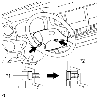
Text in Illustration *1 "TORX" Screw *2 Screw Case Using a T30 "TORX" socket wrench, loosen the 2 "TORX" screws until the groove along the screw circumference catches on the screw case.
Note
Do not drop the steering pad.
-
Pull out the steering pad from the steering wheel and support the steering pad with one hand.
Note
When removing the steering pad, do not pull the airbag wire harness.
-
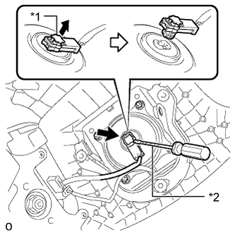
Text in Illustration *1 Lock Plate *2 Tape Using a screwdriver, release the airbag lock plate.
Tech Tips
Tape the screwdriver tip before use.
-
Disconnect the airbag connector from the steering pad.
Note
When handling the airbag connector, take care not to damage the airbag wire harness.
-
Disconnect the horn wire harness connector from the steering pad contact plate and remove the steering pad.
CAUTION:
When storing the steering pad, keep the airbag deployment side facing upward.
-
-
REMOVE STEERING WHEEL ASSEMBLY
-
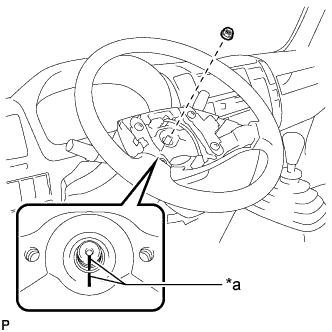
Text in Illustration *a Matchmark Remove the steering wheel assembly set nut.
-
Put matchmarks on the steering wheel assembly and steering main shaft.
-
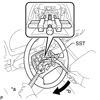
Text in Illustration *a Hold *b Turn Using SST, remove the steering wheel assembly.
- SST
- 09950-50013 ( 09951-05010, 09952-05010, 09953-05020, 09954-05070 )
Note
Apply a small amount of grease to the threads and tip of SST (09953-05020) before use.
-
-
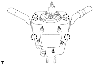
REMOVE STEERING WHEEL COVER SUB-ASSEMBLY
-
Remove the 3 screws and steering wheel cover sub-assembly from the steering wheel assembly.
-
-
REMOVE LOWER STEERING COLUMN COVER
-
Remove the 5 screws.
-
Disengage the 4 claws and remove the lower steering column cover.
-
-
REMOVE UPPER STEERING COLUMN COVER
-
Disengage the 3 claws and separate the steering column cover plate.
-
Remove the upper steering column cover from the steering column.
-
-
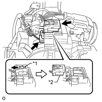
REMOVE WINDSHIELD WIPER SWITCH ASSEMBLY
-
Disconnect the connector.
-
Detach the claw and remove the windshield wiper switch assembly.
-
-
REMOVE SPIRAL CABLE SUB-ASSEMBLY
Note
-
Do not replace the spiral cable with the battery connected and the ignition switch on (IG).
-
Do not rotate the spiral cable with the battery connected and the ignition switch on (IG).
-
Text in Illustration *1 Lock Slider *2 Airbag Connector (Yellow Colored) Pull the lock slider in the direction indicated by the arrow to release the connector lock and disconnect the airbag connector (yellow colored) from the spiral cable sub-assembly.
Note
When handling the airbag connector, take care not to damage the airbag wire harness.
-
Disconnect the connector from the spiral cable sub-assembly.
-
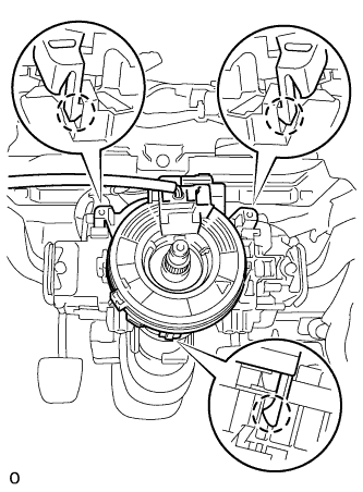
Detach the 3 claws and remove the spiral cable sub-assembly.
-
-
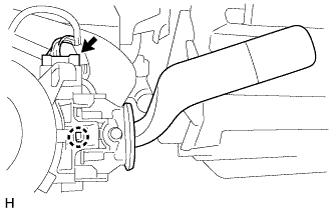
REMOVE HEADLIGHT DIMMER SWITCH ASSEMBLY
-
Disconnect the connector.
-
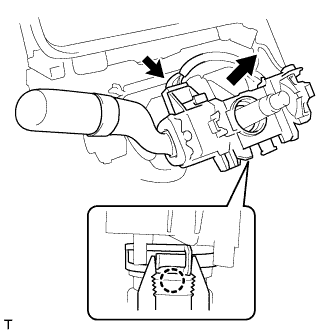
While loosening the band clamp, detach the claw and remove the headlight dimmer switch assembly.
Note
If the claw is pressed forcefully, it will break.
-
-
SEPARATE STEERING MAIN SHAFT ASSEMBLY
-
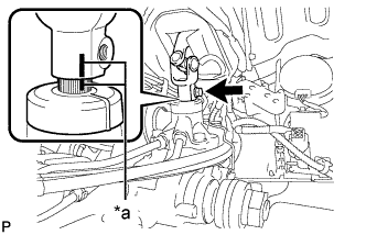
Text in Illustration *a Matchmark Remove the bolt.
-
Slide the steering main shaft assembly toward the steering column assembly.
Note
Do not separate the steering main shaft assembly from the power steering gear assembly.
-
Put matchmarks on the steering main shaft assembly and the power steering gear assembly.
-
Separate the steering main shaft assembly from the power steering gear assembly.
-
-
REMOVE STEERING POST ASSEMBLY
-
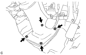
Remove the 4 bolts.
-
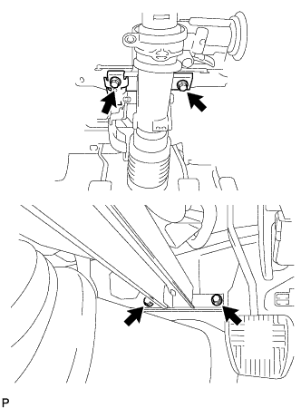
Remove the 4 bolts and steering post assembly.
-