EXHAUST BRAKE RETARDER INSPECTION

-
INSPECT EXHAUST RETARDER ASSEMBLY
-
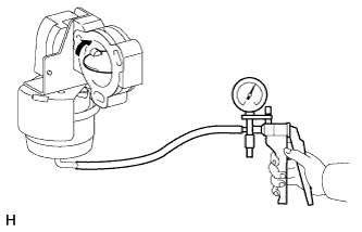
Using a vacuum pump, confirm that the valve fully closes smoothly when applying a vacuum of 53.3 to 80.0 kPa (400 to 600 mmHg).
-
Confirm that the valve fully opens smoothly after exposing the exhaust retarder assembly to atmospheric pressure.
-
-
INSPECT AND ADJUST EXHAUST BRAKE VALVE ASSEMBLY
-
Using a vacuum pump, fully close the valve by applying a vacuum of 86.7 to 93.3 kPa (650 to 700 mmHg).
-
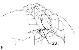
Using SST, inspect the gap between the valve and body.
- SST
- 09240-00020
Standard clearance 0.2 to 0.3 mm (0.00787 to 0.0118 in.) -
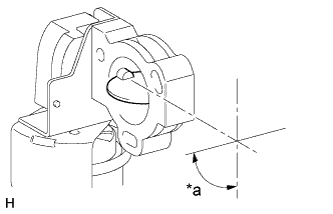
Text in Illustration *a 90° With the valve fully opened after exposing the exhaust retarder assembly to atmospheric pressure, inspect the angle between the valve and body.
-
Loosen the 2 nuts.
-
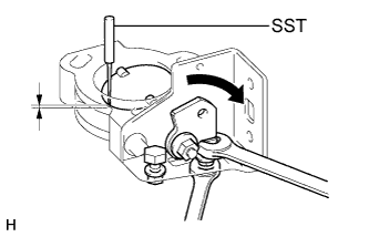
With the exhaust brake valve assembly against the exhaust brake valve stopper bolt as shown in the illustration (with the valve fully closed), adjust the exhaust brake valve stopper bolt so that the gap between the valve and body is within the standard clearance using SST.
- SST
- 09240-00020
Standard clearance 0.2 to 0.3 mm (0.00787 to 0.0118 in.) -
Tighten the nut.
- Torque:
- 5.9 N*m { 60 kgf*cm, 52 in.*lbf }
-
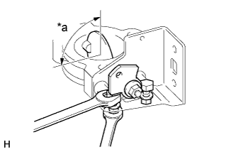
Text in Illustration *a 90° With the exhaust valve lever against the exhaust brake valve stopper bolt as shown in the illustration (with the valve fully opened), adjust the brake valve stopper bolt so that the valve and body are at the standard angle.
Standard 90° -
Tighten the nut.
- Torque:
- 5.9 N*m { 60 kgf*cm, 52 in.*lbf }
-