PARKING BRAKE CABLE INSTALLATION

-
INSTALL NO. 3 PARKING BRAKE CABLE ASSEMBLY
-
Install the No. 3 parking brake cable assembly.
-
Install the No. 3 parking brake cable assembly.
-
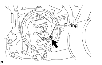
Install the E-ring to the parking brake shoe back plate.
-
-
-
INSTALL PARKING BRAKE SHOE ADJUSTER SUB-ASSEMBLY
-
INSTALL NO. 1 PARKING BRAKE SHOE ASSEMBLY RH OR CENTER
-
INSTALL NO. 2 PARKING BRAKE SHOE ASSEMBLY RH OR CENTER
-
INSTALL PARKING BRAKE SHOE RETURN TENSION SPRING
-
INSTALL FLANGE
-
CHECK PARKING BRAKE INSTALLATION
-
INSTALL PARKING BRAKE DRUM SUB-ASSEMBLY
-
INSTALL FLANGE SET NUT
-
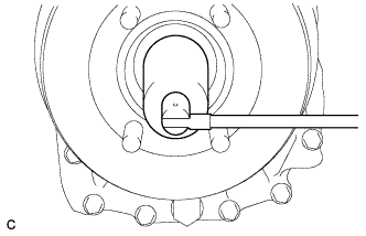
Apply engine oil to a new O-ring, and install it to the companion flange.
-
Pull the parking brake lever fully, and shift into the 1st position.
-
Using a 36 mm socket wrench, install a new transmission output shaft rear set nut.
- Torque:
- 289 N*m { 2947 kgf*cm, 213 ft.*lbf }
-
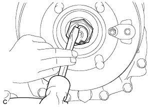
Using a chisel and hammer, stake the transmission output shaft rear set nut.
-
-
INSTALL PROPELLER INTERMEDIATE SHAFT ASSEMBLY
-
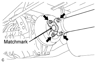
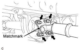
Align the matchmarks on the intermediate shaft flange and parking brake drum.
-
Install the 4 nuts and 4 washers.
- Torque:
- 103 N*m { 1050 kgf*cm, 76 ft.*lbf }
Tech Tips
Engage the parking brake.
-
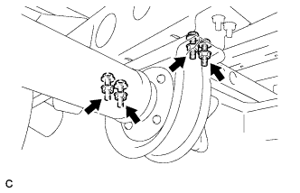
Secure the bolts and install the intermediate shaft assembly to the body with the 4 nuts and 4 washers.
- Torque:
- 52 N*m { 525 kgf*cm, 38 ft.*lbf }
-
-
INSTALL CENTER PROPELLER SHAFT ASSEMBLY (for 4 Joint Type)
-

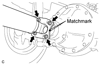
Align the matchmarks on the propeller shaft center flange and the intermediate shaft, and install the 4 washers and 4 nuts.
- Torque:
- 75 N*m { 760 kgf*cm, 55 ft.*lbf }
-
Secure the bolts and install the propeller shaft center to the body with the 4 nuts and 4 washers.
- Torque:
- 52 N*m { 525 kgf*cm, 38 ft.*lbf }
-
-
INSTALL PROPELLER SHAFT ASSEMBLY
-
Align the matchmarks on the propeller shaft flange and intermediate shaft, and temporarily install the 4 washers and 4 nuts.
-
Tighten the 4 nuts.
- Torque:
- 75 N*m { 760 kgf*cm, 55 ft.*lbf }
Tech Tips
Engage the parking brake.
-
Align the matchmarks on the propeller shaft flange and differential.
-
Install the 4 bolts, 4 washers and 4 nuts.
- Torque:
- 75 N*m { 760 kgf*cm, 55 ft.*lbf }
-
-
INSTALL NO. 2 PARKING BRAKE CABLE ASSEMBLY
-
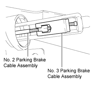
Connect the No. 2 parking brake cable assembly to the No. 3 parking brake cable assembly.
-
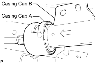
Insert casing cap B into casing cap A. Align the protrusion on casing cap B with the slit of casing cap A using the arrows in the illustration as guides.
-
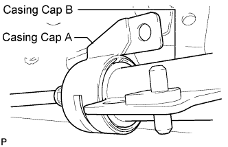
Twist casing caps A and B until their flanges come together (approximately 90°) as shown in the illustration.
-

Connect the flanges to the bracket with the nut.
- Torque:
- 18 N*m { 184 kgf*cm, 13 ft.*lbf }
-
Insert the No. 2 parking brake cable assembly into the room interior.
-
Mount the cable grommet into the floor panel.
-
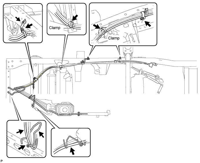
Attach the No. 2 parking brake cable assembly to each cable bracket and 2 new clamps with the bolt and 3 nuts, as shown in the illustration.
- Torque:
- 18 N*m { 184 kgf*cm, 13 ft.*lbf }
-
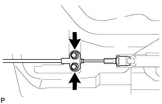
Install the parking brake cable to the floor panel with the 2 bolts.
- Torque:
- 18 N*m { 184 kgf*cm, 13 ft.*lbf }
-
Connect the No. 2 parking brake cable assembly to the parking brake lever's adjusting nut. Temporarily tighten the lock nut.
-
-
ADJUST PARKING BRAKE SHOE CLEARANCE
-
INSPECT PARKING BRAKE LEVER TRAVEL
Tech Tips
See Pub. No. RM1008E, page 33-1.
-
ADJUST PARKING BRAKE LEVER TRAVEL
Tech Tips
See Pub. No. RM1008E, page 33-1.
-
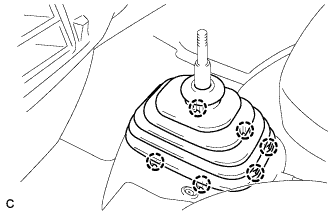
INSTALL SHIFT LEVER BOOT COVER
-
Install the shift lever boot cover with the 3 clips.
-
-
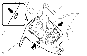
INSTALL SHIFTING HOLE COVER SUB-ASSEMBLY
-
Engage the 6 claws, and install the shifting hole cover sub-assembly.
-
-
INSTALL PARKING BRAKE HOLE COVER
-
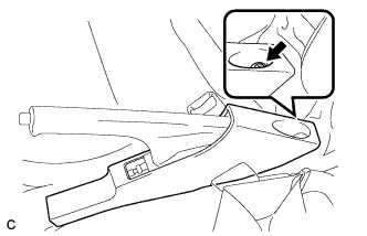
Install the parking brake hole cover with the screw.
-
-
INSTALL SHIFT LEVER KNOB SUB-ASSEMBLY
-
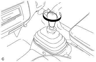
Turn the shift lever knob clockwise and install the shift lever knob sub-assembly.
-