POWER STEERING LINK INSTALLATION

-
INSTALL STEERING KNUCKLE ARM LH
-
Install the steering knuckle arm LH to the steering knuckle LH with the nut.
- Torque:
- 685 N*m { 6985 kgf*cm, 505 ft.*lbf }
Note
Further tighten the nut up to 60° if the holes for the cotter pin are not aligned.
-
Install a new cotter pin.
-
-
INSTALL STEERING KNUCKLE ARM RH
Tech Tips
Perform the same procedure on the LH side.
-
INSTALL TIE ROD END SUB-ASSEMBLY LH
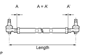
-
Screw the tie rod ends and lock nuts by an equivalent amount into both ends of the tie rod.
-
Adjust the length of the tie rod assembly.
Length 1425 mm (56.10 in.) -
Temporarily tighten the tie rod end lock nuts.
-
After toe-in adjustment, torque the lock nut.
- Torque:
- 175 N*m { 1784 kgf*cm, 129 ft.*lbf }
-
-
INSTALL TIE ROD END SUB-ASSEMBLY RH
Tech Tips
Perform the same procedure on the LH side.
-
INSTALL TIE ROD ASSEMBLY
-
Install the tie rod to the right and left knuckle arm, then install the 2 nuts.
- Torque:
- 195 N*m { 1987 kgf*cm, 143 ft.*lbf }
Note
Further tighten the nut up to 60° if the holes for the cotter pin are not aligned.
-
Install a new cotter pin.
-
-
INSTALL STEERING DRAG LINK ASSEMBLY
-
Install the drag link to the knuckle arm and steering knuckle, then install the nuts.
- Torque:
- 195 N*m { 1987 kgf*cm, 143 ft.*lbf }
Note
Further tighten the nut up to 60° if the holes for the cotter pin are not aligned.
-
Install a new cotter pin.
-
-
INSTALL FRONT WHEELS
- Torque:
- 515 N*m { 5252 kgf*cm, 380 ft.*lbf }
-
INSPECT STEERING WHEEL CENTER POINT
-
INSPECT AND ADJUST FRONT WHEEL ALIGNMENT
-
(See Pub. No. RM1008E, page 26-2)
-