VANE PUMP INSTALLATION

-
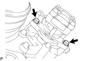
INSTALL VANE PUMP ASSEMBLY
-
Install a new O-ring to the vane pump assembly.
Note
Install the O-ring securely until it touches the bottom of the groove.
-
Install the vane pump assembly with the 2 bolts.
- Torque:
- 47 N*m { 479 kgf*cm, 35 ft.*lbf }
Note
-
There should be no clearance between the vane pump assembly and engine case.
-
Be careful not to allow the O-ring to get caught between the parts.
-
-
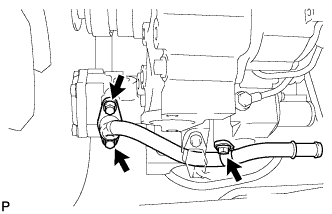
INSTALL POWER STEERING SUCTION PORT UNION
-
Coat a new O-ring with power steering fluid and install it to the power steering suction port union.
-
Install the power steering suction port union to the vane pump assembly and setting plate with the 3 bolts.
- Torque:
- 29 N*m { 291 kgf*cm, 21 ft.*lbf }
-
-
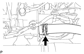
CONNECT NO. 2 OIL RESERVOIR TO PUMP HOSE
-
Connect the No. 2 oil reservoir to pump hose to the power steering suction port union, and slide the clip to secure it.
-
-
INSTALL OIL PUMP TO GEAR BOX TUBE
-
Install the No. 1 hose support bracket and oil pump to gear box tube with the 4 bolts.
- Torque:
- 29 N*m { 291 kgf*cm, 21 ft.*lbf }
-
Connect the oil pump to gear box tube to the No. 1 hose support bracket with nut.
- Torque:
- 44 N*m { 449 kgf*cm, 32 ft.*lbf }
-
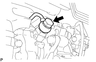
Install the oil pump to gear box tube to the vane pump with a new gasket and the union bolt.
- Torque:
- 49 N*m { 500 kgf*cm, 36 ft.*lbf }
-
-
CONNECT PRESSURE FEED HOSE
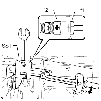
Text in Illustration *a Hold *b Turn *c Fulcrum Length
-
Using a wrench, secure the oil pump to gear box tube.
-
Using SST, connect the pressure feed hose to the oil pump to gear box tube.
- SST
- 09922-10010
- Torque:
- without SST
- 44 N*m { 449 kgf*cm, 32 ft.*lbf }
- with SST
- 30 N*m { 300 kgf*cm, 22 ft.*lbf }
Note
-
Use a torque wrench with a fulcrum length of 300 mm (11.81 in.).
-
This torque value is effective when SST is parallel to the torque wrench.
-
-
INSTALL RADIATOR PIPE SUB-ASSEMBLY
-
Install a new O-ring and the radiator pipe sub-assembly with the 2 bolts.
- Torque:
- 29 N*m { 291 kgf*cm, 21 ft.*lbf }
-
-
CONNECT OUTLET RADIATOR HOSE
-
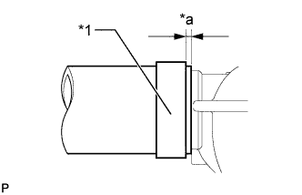
Text in Illustration *1 Hose Clamp *a 10.0 mm (0.394 in.) or less Securely push the outlet radiator hose onto the radiator assembly until it contacts the stopper, and then install the hose clamp in the location shown in the illustration.
-
-
ADD POWER STEERING FLUID
-
ADD ENGINE COOLANT
-
BLEED POWER STEERING SYSTEM
-
Check the fluid level Click here.
-
Jack up the front of the vehicle and support it with stands.
-
Turn the steering wheel.
-
With the engine stopped, turn the steering wheel slowly from lock to lock several times.
-
-
Lower the vehicle.
-
Start the engine.
-
Run the engine at idle for a few minutes.
-
-
Turn the steering wheel.
-
With the engine idling, turn the steering wheel left or right to the full lock position and keep it in that position for 2 to 3 seconds, then turn the steering wheel to the opposite full lock position and keep it there for 2 to 3 seconds (*1).
-
Repeat this procedure (*1) several times.
-
-
Stop the engine.
-
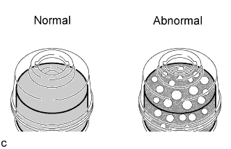
Check for foaming or emulsification.
Tech Tips
If the system has to be bled twice because of forming or emulsification, be sure to check for fluid leaks in the system.
-
Check the fluid level Click here.
-
-
INSPECT FOR COOLANT LEAK
-
INSPECT FOR POWER STEERING FLUID LEAK
-
CHECK POWER STEERING FLUID LEVEL
-
Keep the vehicle level.
-
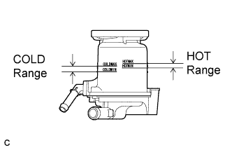
With the engine stopped, check the fluid level in the fluid reservoir.
If necessary, add fluid.
Fluid ATF DEXRON II or III, or equivalent. Tech Tips
If the fluid is hot, check that the fluid level is within the HOT range on the fluid reservoir. If the fluid is cold, check that the fluid level is within the COLD range.
-
Start the engine and run it at idle.
-
Turn the steering wheel from lock to lock several times to raise fluid temperature.
Fluid temperature 50 to 60°C (122 to 140°F) -
Check for foaming or emulsification.
If foaming or emulsification is identified, bleed the power steering system Click here.
-
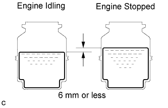
With the engine idling, measure the fluid level in the fluid reservoir.
-
Stop the engine.
-
Wait a few minutes and remeasure the fluid level in the fluid reservoir.
Maximum fluid level rise 6 mm (0.24 in.) If any problem is found, bleed the power steering system Click here.
-
Check the fluid level.
-
-
CHECK COOLANT LEVEL OF RESERVOIR